Disc-molding mold molded product and moloding machine

a technology of disc-molding molds and molded products, which is applied in the direction of dough shaping, manufacturing tools, instruments, etc., can solve the problems of excessive cooling of the outer peripheral edge portion of the cavity space, large amount of heat radiation, and generation of temperature gradients insid

Inactive Publication Date: 2005-10-06
SUMITOMO HEAVY IND LTD +1
View PDF1 Cites 10 Cited by
  • Summary
  • Abstract
  • Description
  • Claims
  • Application Information

AI Technical Summary

Benefits of technology

[0025] In this case, since the medium passage of the non-stamper-side disc-shaped member has a greater depth at a portion corresponding to the heat insulating section as compared with the remaining portions, on the non-stamper side, the temperature of resin does not increase excessively in the vicinity of the outer peripheral edge. Accordingly, a large temperature difference is not produced between a high-temperature portion and a low-temperature portion of a disc substrate when it is removed after the mold is opened, whereby a difference in shrinkage percentage is not produced between the high-temperature portion and a low-temperature portion. As a result, the disc substrate can have an even thickness.

Problems solved by technology

However, in the conventional disc-molding mold, generation of a temperature gradient within the cavity space is suppressed; however, since the outer peripheral edge portion of the cavity space is located in the vicinity of the peripheral edge of the disc-molding mold, a large quantity of heat is radiated therefrom to the outside of the disc-molding mold, whereby the outer peripheral edge portion of the cavity space is cooled excessively.
As a result, the degree of transfer locally decreases in the vicinity of the outer peripheral edge of the cavity space, and quality of disc substrates is deteriorated.

Method used


Image

  • Disc-molding mold molded product and moloding machine
  • Disc-molding mold molded product and moloding machine
  • Disc-molding mold molded product and moloding machine

Examples


Embodiment Construction

[0031] An embodiment of the present invention will next be described in detail with reference to the drawings.

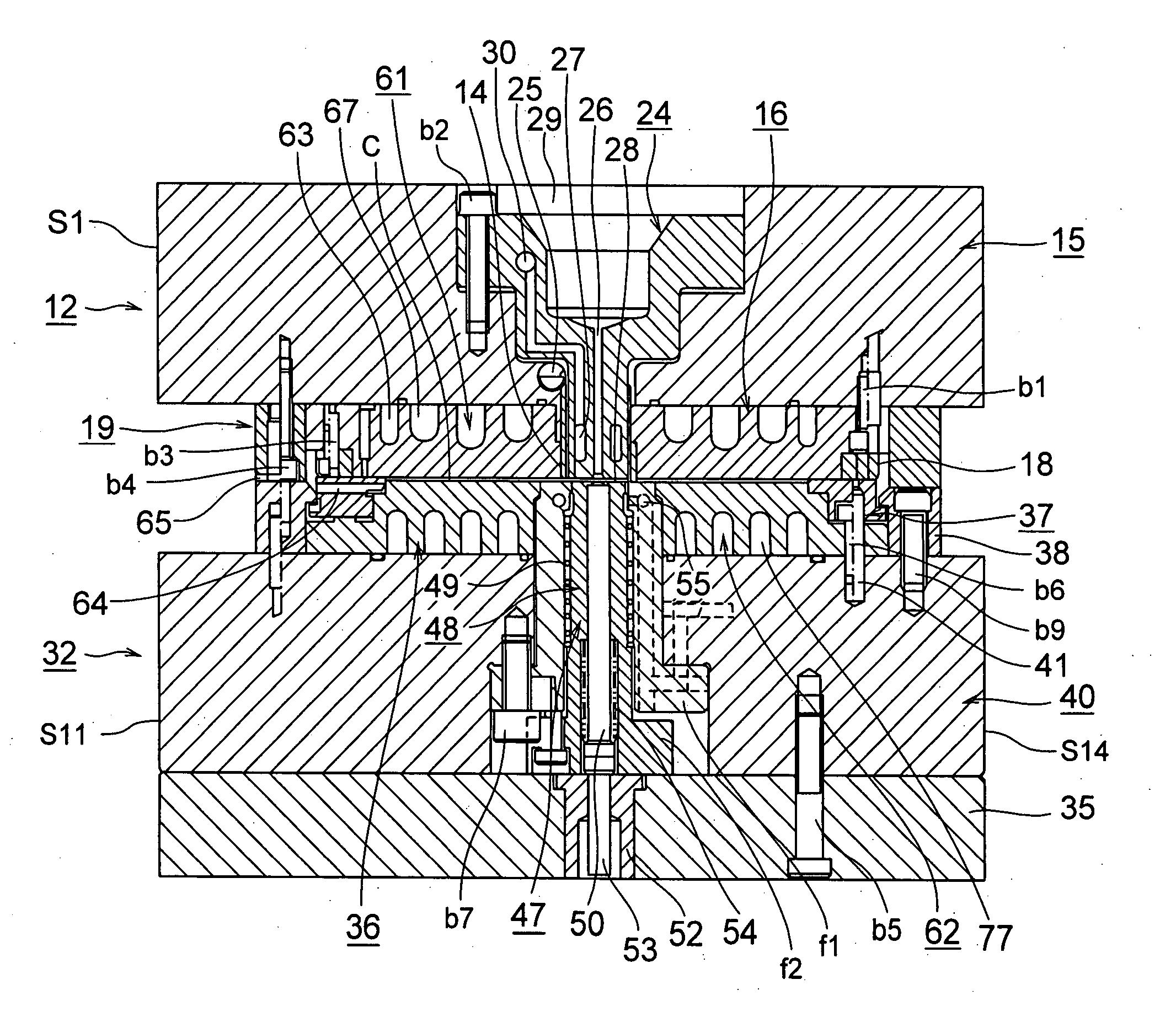
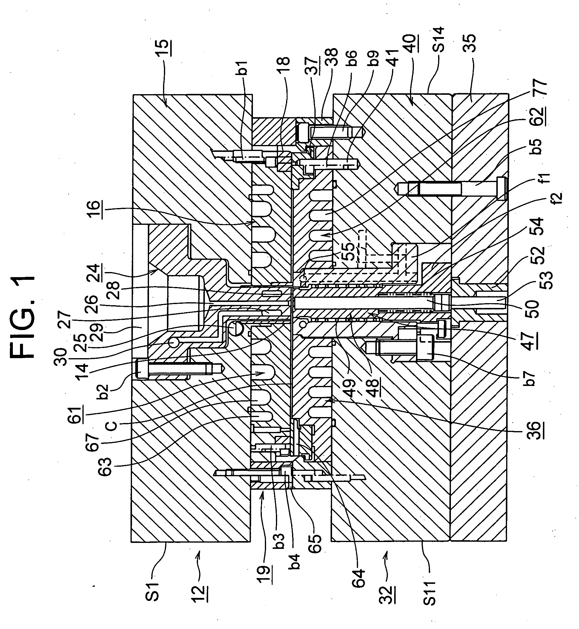
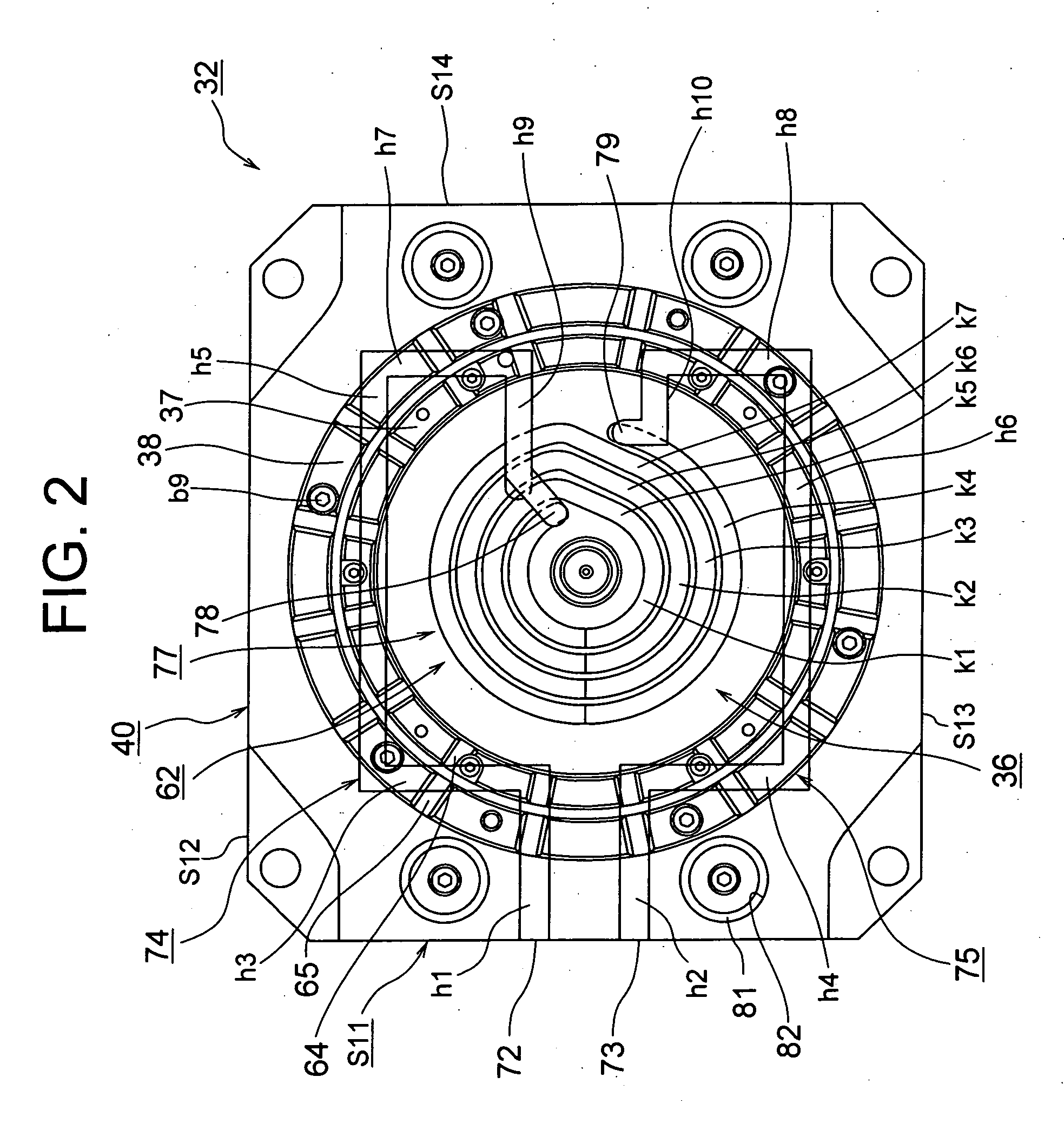
[0032]FIG. 1 is a sectional view showing a main portion of the disc-molding mold according to the embodiment of the present invention; FIG. 2 is a front view showing a main portion of a movable mold assembly according to the embodiment of the present invention; and FIG. 3 is an enlarged view showing a main portion of the disc-molding mold according to the embodiment of the present invention.

[0033] In the drawings, reference numeral 12 denotes a stationary mold assembly that is attached to an unillustrated stationary platen via an unillustrated mount plate and by use of unillustrated bolts. The stationary mold assembly 12 is composed of a base plate 15 serving as a first support member; a mirror-surface disc 16 serving as a first disc-shaped member and attached to the base plate 15 by use of bolts b1; and a sprue bush 24 disposed within the base plate 15 to be positioned wi...


PUM

PropertyMeasurementUnit
temperatureaaaaaaaaaa
cooling capacityaaaaaaaaaa
heat insulatingaaaaaaaaaa

Abstract

An object is to provide a disc-molding mold which can increase the degree of transfer of a pattern of a stamper to thereby improve quality of molded products, as well as a molded product and a molding machine. In the vicinity of the outer peripheral edges of first and second disc-shaped members, the cooling capacity of the medium flow passage of the stamper-side disc-shaped member is made lower than the cooling capacity of the medium flow passage of the non-stamper-side disc-shaped member. On the stamper side, the quantity of heat radiated from the outer peripheral edge of the stamper-side disc-shaped member to the outside of the disc-molding mold can be reduced, whereby over-cooling of the stamper-side disc-shaped member can be prevented. As a result, a local deterioration in the degree of transfer, which would otherwise occur in the vicinity of the outer peripheral edge of the cavity space (C), can be prevented, and thus the degree of transfer of the fine pattern can be improved over the entire cavity space (C) As a result, quality of molded products can be improved.

Description

TECHNICAL FIELD [0001] The present invention relates to a disc-molding mold, a molded product, and a molding machine. BACKGROUND ART [0002] Conventionally, in a molding machine, such as an injection molding machine, for molding a product such as a disc substrate, resin melted within a heating cylinder is charged into a cavity space in a disc-molding mold, and is then cooled and hardened in the cavity space so as to obtain a disc substrate. [0003] For such a molding process, the above-mentioned injection molding machine includes the disc-molding mold consisting of a stationary mold assembly and a movable mold assembly; an injection apparatus for charging resin into a cavity space; and a mold clamp apparatus for bringing the movable mold assembly into contact with the stationary mold assembly and separating the movable mold assembly from the stationary mold assembly. The mold clamp apparatus is operated so as to advance and retract the movable mold assembly to thereby close, clamp, an...

Claims


Application Information

Patent Timeline
Patent Type & Authority Applications(United States)
IPC IPC(8): B29C33/04B29C45/26B29C45/73B29D11/00G11B7/26
CPCB29C45/2642G11B7/263Y10S425/81
Inventor INADA, YUICHISAKAMOTO, YASUYOSHIHIKI, KATSUYUKI
Owner SUMITOMO HEAVY IND LTD
Why Eureka
Try Eureka