
Stackable chair with modular slide-on seat back

a seat back and modular technology, applied in the field of stackable chairs, can solve the problems of affecting the stability of the chair, the loosening of the fastener used to hold the seat back assembly to the frame, and the aging of the chair, so as to reduce material and labor costs, facilitate and inexpensively manufacture and assembly, and reduce the effect of material and labor costs

Inactive Publication Date: 2005-05-12
MITY-LITE
View PDF6 Cites 25 Cited by
  • Summary
  • Abstract
  • Description
  • Claims
  • Application Information

AI Technical Summary

Benefits of technology

[0015] Broadly, the present invention is a stackable chair having fully-upholstered, multi-contoured, polymer composite seat back assembly. The seat back is easily and inexpensively manufactured and assembled to the frame of the chair in a slide-on manner, with no structural supports or fasteners being visible after assembly. The novel chair provides comfort, durability, style and cost-effectiveness as a result of its incorporation of molded-in components that reduce material and labor costs. Additionally, the novel seat back weighs considerably less than those incorporated in prior art stackable chairs, such that lifting and stacking of the chair are easier and less strenuous.
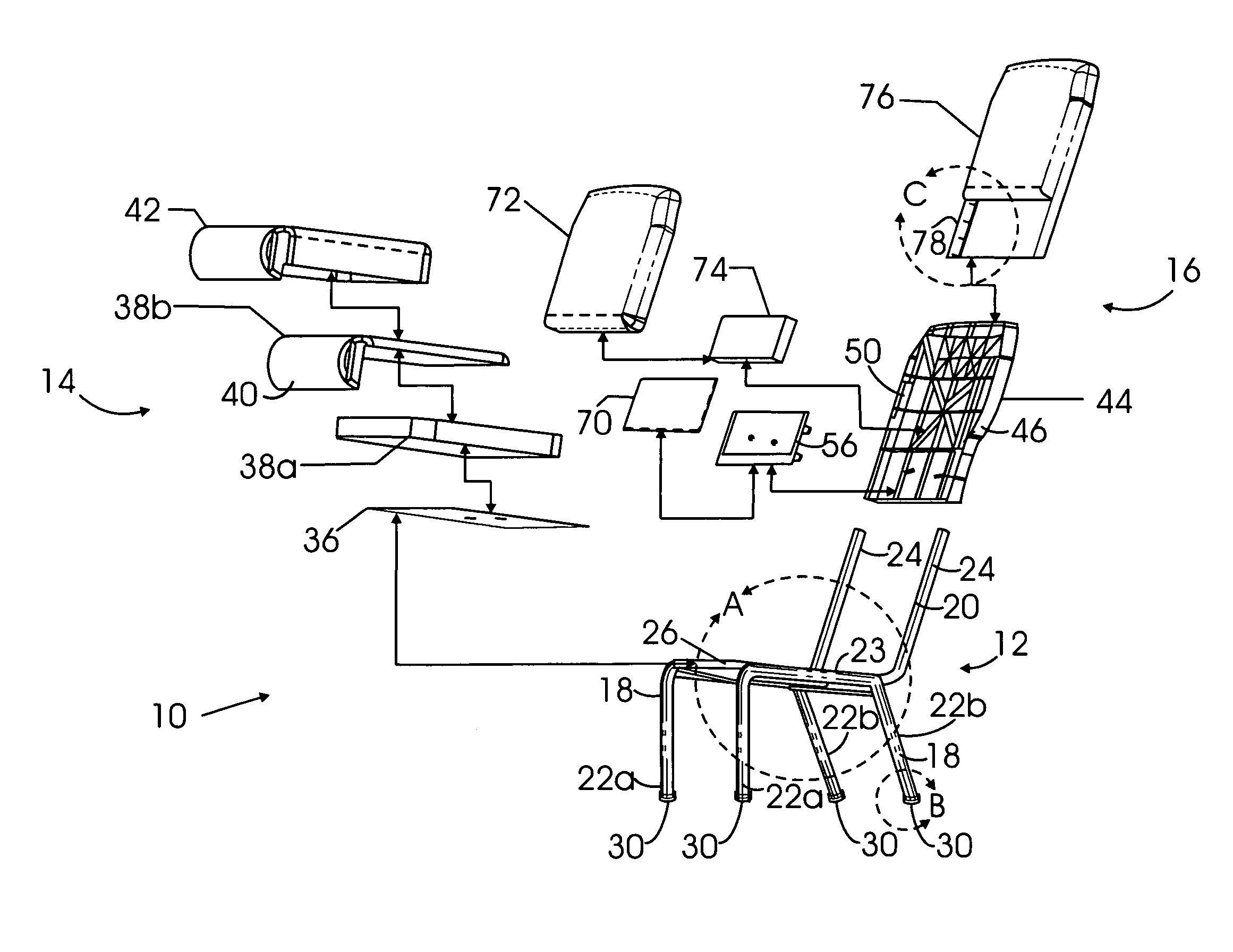
[0018] The seat and back frame member includes a pair of parallel elements, the front portions of which extend longitudinally (front to back) and are oriented substantially horizontal, or at a slight downward angle from front to rear. The rear portions of the parallel elements of the seat and back frame member are bent upward to define a pair of parallel, upstanding stile portions on which the seat back module of the chair is supported in a slide-on arrangement, as described below. The parallel elements of the seat and back frame member are connected at the front by a horizontal transverse element that defines a nose, or front rail, of the chair. The longitudinal portion of each of the side frame members is joined to a longitudinal portion of the seat and back frame member, such that the latter is rigidly supported therebetween. The assembly is held in a square, parallel, upstanding relationship by a pair of front and rear stretchers, or torsion bars, that respectively extend between the front chair legs and the rear chair legs. A plastic glide having an arcuate lower end snaps into the lower end of each the legs to prevent marring of a floor on which the chair is placed or slid.

Problems solved by technology

However, some problems have been found to exist with this type of seat back assembly over time or with hard use.
For example, because of the nature of the typical environment in which a stackable chair is used, including its constant handling and mishandling over a relatively short period of time, the fasteners used to hold the seat back assembly to the frame can loosen, and eventually, migrate out of their installation holes.
As will be appreciated, loose or lost seat back fasteners can result not only in damage to the chair, but an uncomfortable or even dangerous sitting experience for the client, as well.
Another problem with prior art stackable chairs involves their lack of comfort.
Because of the base material typically used in the seat back (i.e., solid wood or plywood), the back cannot be easily configured to accommodate the multiple contours of the human back, particularly the lumbar region.
Because of this, the back of a person sitting in a conventional stackable chair over even a short period of time can become very stressed and painful.
Additionally, stackable chairs incorporating current assembly techniques require the use of relatively dense woods or composite materials that are too heavy and cumbersome to be lifted and / or efficiently stacked for storage.
A long-felt but as yet unsatisfied need therefore exists in the field of commercial and institutional furniture for a stackable chair that is easily and inexpensively manufactured and assembled, and that has a seat back that can be easily and reliably installed without fasteners that can come loose during hard use.

Method used


Image

  • Stackable chair with modular slide-on seat back
  • Stackable chair with modular slide-on seat back
  • Stackable chair with modular slide-on seat back

Examples


Embodiment Construction

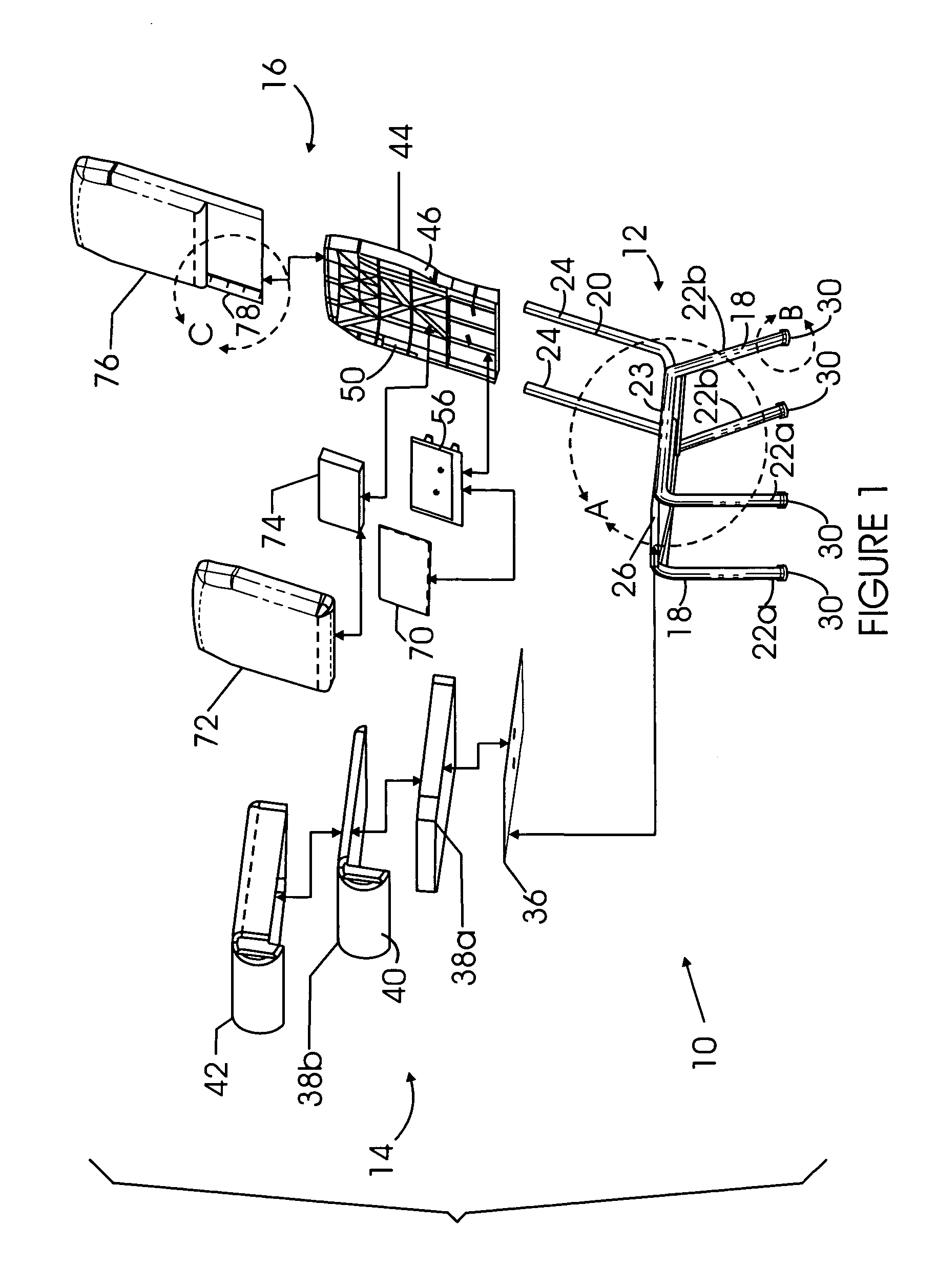
[0043] An exploded perspective view of an exemplary embodiment of a stackable chair 10 in accordance with the present invention is illustrated in FIG. 1. As illustrated therein, the chair comprises a plurality of assemblies, or modules, including a frame module 12, a seat module 14, and a back module 16.

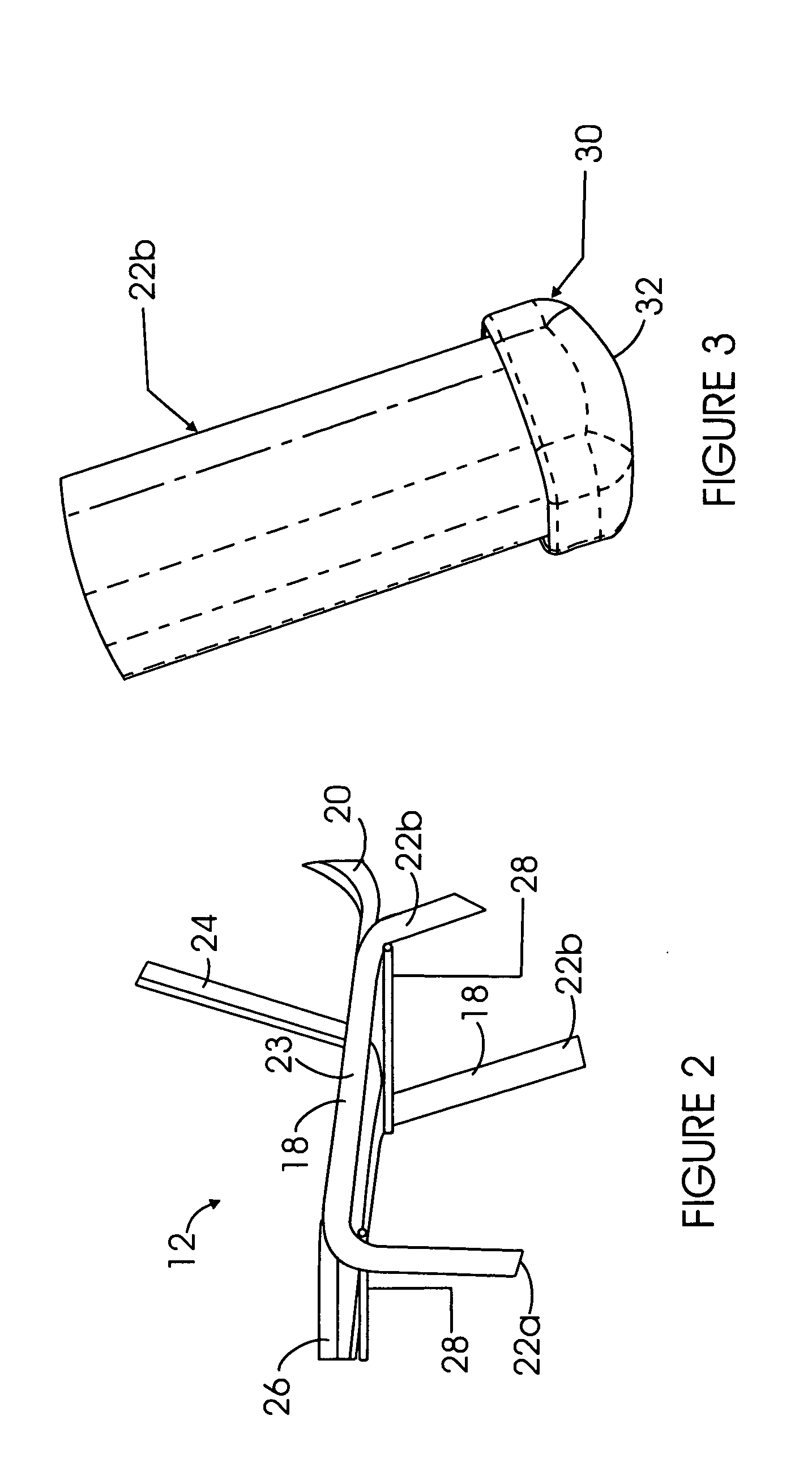
[0044] As illustrated in detail A of FIG. 1 and the enlarged view thereof of FIG. 2, the frame module 12 comprises a pair of generally inverted U-shaped tubular side frame members 18, and a tubular seat and back frame member 20. The tubular members 18 and 20 are preferably formed of steel or aluminum tubing, with open ends, and, as illustrated, they are generally square in cross-section. It will be appreciated, however, that that other cross-sectional shapes are possible, and may be preferable, depending on the application at hand.

[0045] Each of the side frame members 18 includes a pair of substantially vertical portions, each of which forms a front chair leg 22a and a rear chair l...


PUM


Abstract

A stackable chair includes first, second, and third frame members. Each of the first and second frame members forms a front and rear chair leg joined by a seat side rail. The third frame member has opposed side portions respectively joined to the seat side rails, a transverse front nose portion, and a pair of upwardly-extending back stiles. A cushioned and upholstered seat module assembly is attached to the seat side rails. A back module assembly includes a contoured, cushioned, and upholstered back base element having a pair of channels formed therein that are configured and located so as to receive and conceal the stiles when the back module assembly is slid onto the stiles, whereby the back module assembly is attachable to the stiles along the channels. A lower lumbar support element is advantageously attached to the lower portion of the back base element.

Description

CROSS-REFERENCE TO RELATED APPLICATION [0001] This application claims the benefit, under 35 U.S.C. Section 119(e), of co-pending provisional application No. 60 / 515,724, filed Oct. 30, 2003, the disclosure of which is incorporated by reference.FEDERALLY-SPONSORED RESEARCH OR DEVELOPMENT [0002] (Not Applicable) BACKGROUND OF THE INVENTION [0003] 1. Field of the Invention [0004] The present invention relates to generally to the field of commercial and institutional furniture. In particular, the present invention, in one aspect, relates to a stackable chair having a modular, fully upholstered, multi-contoured, composite, slide-on seat back that requires no visible structural supports or fasteners for its assembly. In another aspect, the present invention relates to a method for assembling the seat back of the chair. [0005] 2. Related Art [0006] Consumers of modern commercial and institutional furniture demand comfort, durability, and style in their seating choices, and in view of the hi...

Claims


Application Information

Patent Timeline
IPC IPC(8): A47C3/04A47C7/18A47C7/40
CPCA47C3/04A47C7/40A47C7/18
Inventor BERTOLINI, JAMESHORN, CHARLES A.LARGE, JONATHANHARLAN, JEFFREY LAWRENCE
Owner MITY-LITE
Learn More