Disk Brake Assembly

a technology of brake assembly and disk, which is applied in the direction of shrinkage connection, mechanical apparatus, fastening means, etc., can solve the problems of high cost and enormous manufacturing outlay, and achieve the effect of preventing it from falling out, reducing manufacturing costs, and reducing the risk of possible rejecting parts

Inactive Publication Date: 2011-10-20
LUCAS AUTOMOTIVE GMBH
View PDF2 Cites 0 Cited by
  • Summary
  • Abstract
  • Description
  • Claims
  • Application Information

AI Technical Summary

Benefits of technology

[0032]The present invention further relates to a method of manufacturing a disk brake assembly, wherein the disk brake assembly comprises a brake anchor plate as well as a brake pad assembly, the method being characterized in that, in order to connect the brake anchor plate to a guide element having the previously described features, the step of pressing the guide element into a location opening provided on the brake anchor plate is carried out. In order additionally to secure the guide element in the location opening, the, in press-fit direction, rear portion of the location opening may optionally additionally be caulked so that a projection and / or bead thus produced secures the guide element accommodated in the location opening and prevents it from falling out. Whereas in known methods of manufacturing and assembling disk brake assemblies the guide element in the form of a stud bolt is screwed into a location opening provided in the brake anchor plate, in the present method the press-fitting step is carried out instead. This has the advantage that the location opening need not, as in the background art, be provided with a corresponding internal thread, with the result that the manufacturing costs may be substantially reduced. Thus, on the one hand, the thread-cutting production step as such no longer applies and, on the other hand, the risk of possible reject parts (if the thread has not been properly cut) and possible re-working is also reduced.
[0033]By using a guide element having the previously described features, in particular a textured surface, it is guaranteed that alternative method steps, such as are generally known from the press-fit method, for example honing of the parts that are to be connected, are not necessary. The textured surface enables a greater permissible variation with regard to the interference fit that is to be provided between guide element and location opening.

Problems solved by technology

So, unlike in the background art, it is not necessary to smooth and / or hone the location bore or to grind a smooth surface on the elements that are to be press-fitted therein, which would involve an enormously high manufacturing outlay and lead to high costs.

Method used


Image

  • Disk Brake Assembly
  • Disk Brake Assembly
  • Disk Brake Assembly

Examples


Embodiment Construction

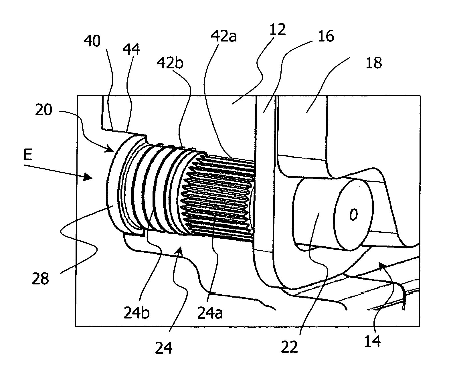
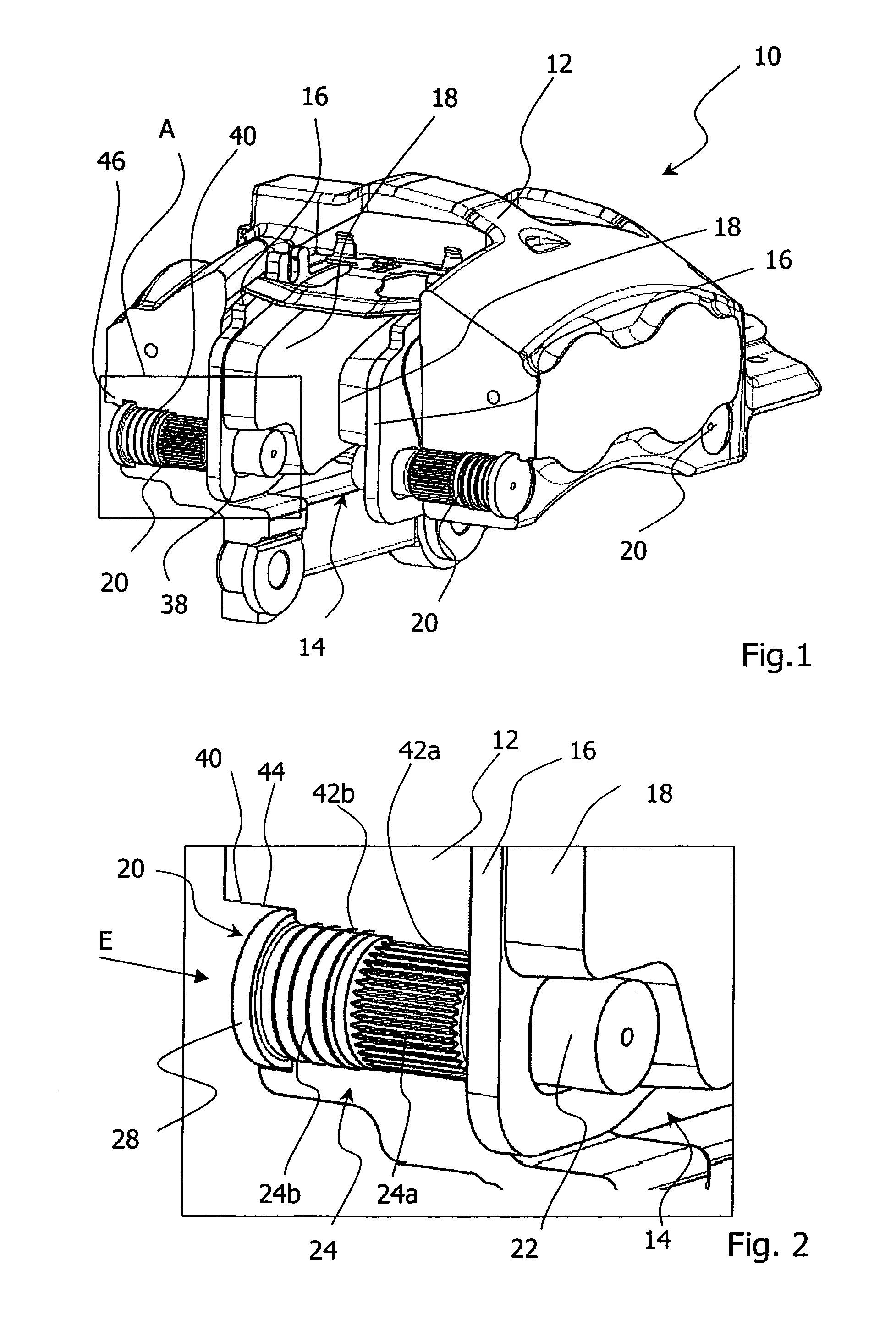
[0038]In FIG. 1 a disk brake assembly according to the invention is shown in a part-sectional perspective view and generally denoted by the reference character 10. The disk brake assembly 10 comprises a brake anchor plate 12, which is used to connect the disk brake assembly 10 to a vehicle, as well as a brake pad assembly 14. The brake pad assembly 14 comprises the supporting plates 16 and the brake pads 18 disposed thereon. Guide elements 20 (in FIG. 1, three of four are shown) are accommodated in location openings 40 of the brake anchor plate 12 and are used to guide and support the brake pad assembly 14 of the disk brake assembly 10 according to the invention. For this purpose, each of the guide elements 20 comprises a first portion 22, on which the brake pad assembly 14 is guided and supported for example, as shown in FIG. 1, by means of corresponding location openings 38 in the supporting plates 16.

[0039]As may be seen clearly in FIG. 2, a detail view of the detail A in FIG. 1,...


PUM

PropertyMeasurementUnit
diameteraaaaaaaaaa
hardnessaaaaaaaaaa
forcesaaaaaaaaaa

Abstract

The invention relates to a disk brake assembly comprising a brake anchor plate for fastening to a vehicle as well as a brake pad assembly, wherein the brake anchor plate has at least one location opening for receiving a guide element that has a first portion for guiding and supporting the brake pad assembly and a second portion for connecting to the brake anchor plate. For simplified manufacture while retaining a permanently reliable mode of operation, it is provided that the second portion has a textured surface, by which the guide element may be press-fitted at least partially into the location opening.

Description

CROSS-REFERENCE TO RELATED APPLICATIONS[0001]This application is a national stage of International Application No. PCT / EP2009 / 008149 filed Nov. 16, 2009, the disclosures of which are incorporated herein by reference in entirety, and which claimed priority to German Patent Application No. 10 2008 058 975.6 filed Nov. 25, 2008, the disclosures of which are incorporated herein by reference in entirety.BACKGROUND OF THE INVENTION[0002]The invention relates to a disk brake assembly comprising a brake anchor plate for fastening to a vehicle as well as a brake pad assembly. The brake anchor plate has at least one location opening for receiving a guide element that has a first portion for guiding and supporting the brake pad assembly and a second portion for connecting to a brake anchor plate.[0003]Such disk brake assemblies are well known from the background art. Thus, for example the documents DE 103 12 478 A1, and corresponding U.S. Pat. No. 7,201,258 B2, both of which are incorporated b...

Claims


Application Information

Patent Timeline
Patent Type & Authority Applications(United States)
IPC IPC(8): F16D65/095B23P11/02F16B4/00
CPCY10T29/49863F16D65/095
Inventor ZENZEN, GUIDOBECKER, MARCO
Owner LUCAS AUTOMOTIVE GMBH
Why Eureka
Try Eureka