

Image processing apparatus, network camera system, image processing method and program
a network camera and image processing technology, applied in the field of image processing apparatus, can solve problems such as the difficulty of a user to understand which area of the captured image transmitted from the camera unit is changing
- Summary
- Abstract
- Description
- Claims
- Application Information
AI Technical Summary
Benefits of technology
Problems solved by technology
Method used
Image

Examples
first embodiment
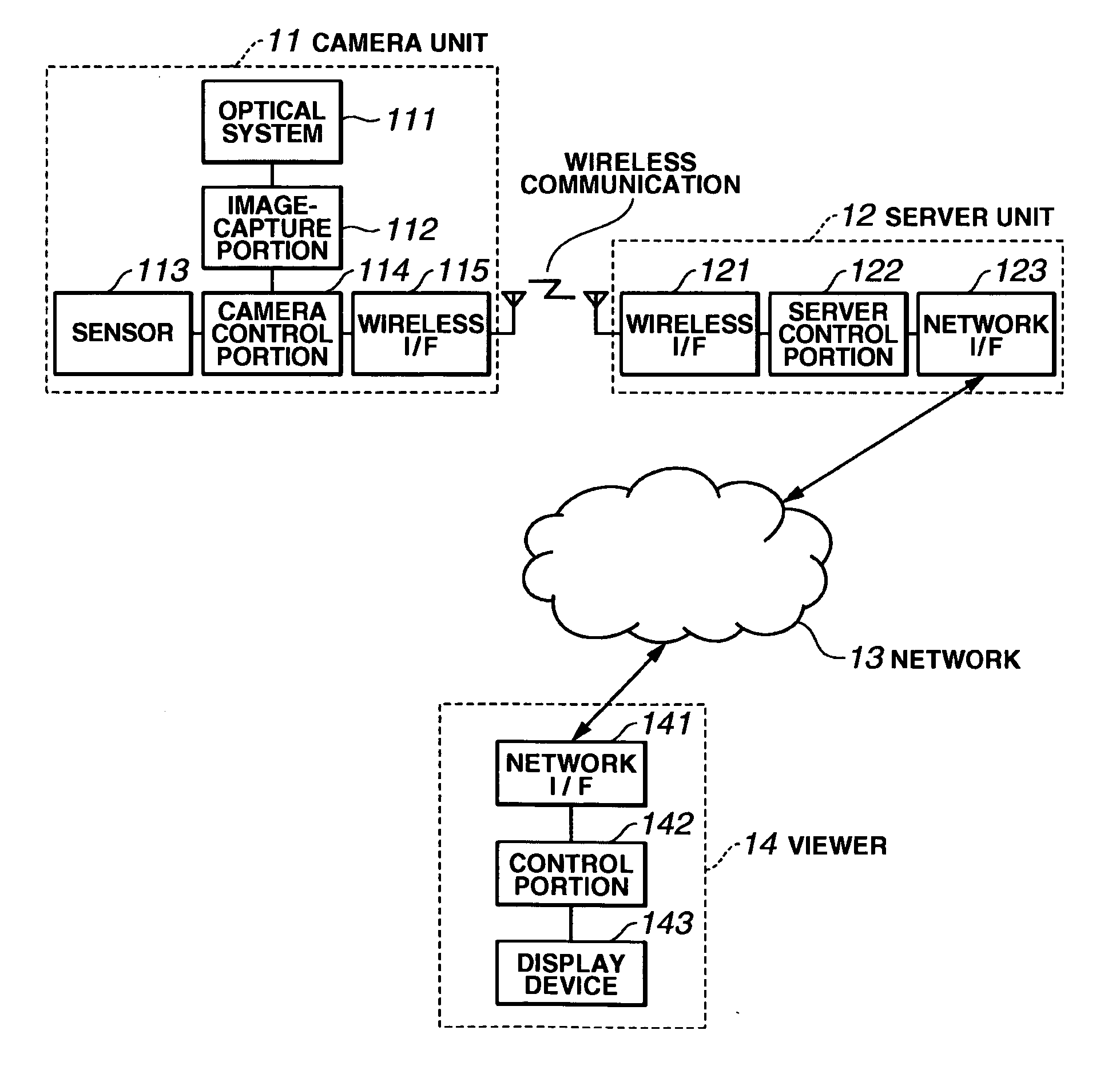
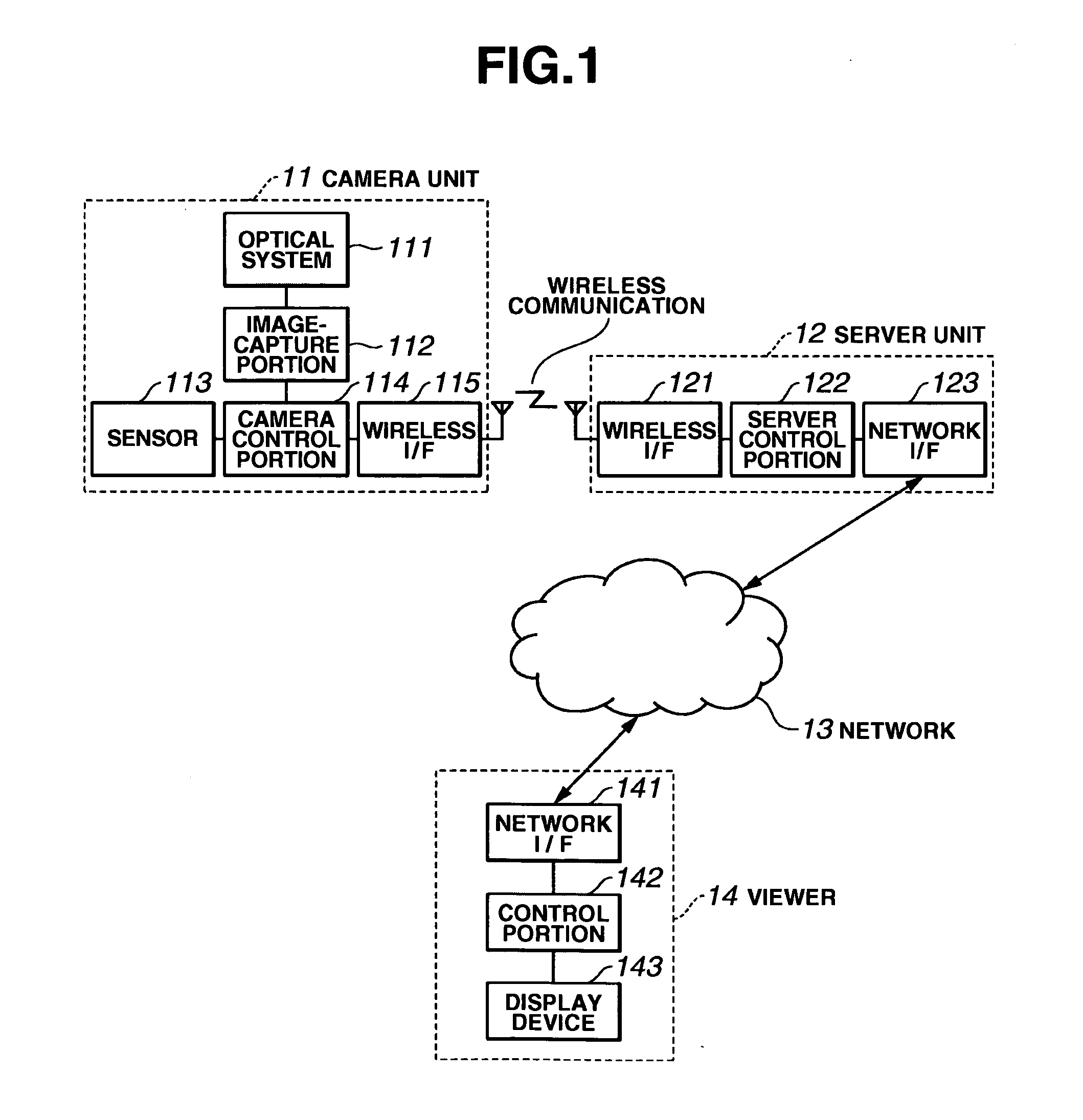
[0039]FIG. 1 is a block diagram showing an example of the hardware construction of a network camera system according to a first embodiment of the invention. The network camera system includes a camera unit 11, a server unit 12, a network 13 and a viewer 14. The camera unit 11 includes an optical system 111, an image-capture portion 112, a sensor 113, a camera control portion 114 and a wireless interface (I / F) 115. The server unit 12 includes a wireless I / F 121, a server control portion 122 and a network I / F 123. The viewer 14 includes a network I / F 141, a control portion 142 and a display device 143.
[0040] The optical system 111 is used for capturing an image. The sensor 113 detects a change in circumstances surrounding the camera unit 11 and a direction in which an area where such a change has occurred exists. The image capture portion 112 includes a CCD (charge-coupled device) or a CMOS (complementary metal oxide semiconductor) image sensor. The camera control portion 114 perform...
second embodiment
[0076] A network camera system according to a second embodiment of the invention differs from the first embodiment in the method of detecting a change in circumstances and extracting a partial image.
[0077] In the network camera system according to the second embodiment, the hardware arrangement, the appearance of a camera unit and a server unit, the construction of the camera unit and the server unit, and the arrangement of sensors are the same as those of the first embodiment shown in FIG. 1 to FIGS. 6A and 6B, and are, therefore, omitted from the following discussion.
[0078] In the second embodiment, a surrounding image is captured at preset timing in the normal situation where there is no change. Then, the surrounding image is stored in the memory 514 shown in FIG. 5 as a comparative surrounding image. Such timing of capturing the surrounding image can be obtained, for example, by a method of capturing an image at intervals of a predetermined period of time with use of a timer. ...
third embodiment
[0088] A network camera system according to a third embodiment of the invention differs from the first embodiment and the second embodiment in an image transmission process and an image display process.
[0089] In the network camera system according to the third embodiment, the hardware arrangement, the appearance of a camera unit and a server unit, the construction of the camera unit and the server unit, and the arrangement of sensors are the same as those of the first embodiment shown in FIG. 1 to FIGS. 6A and 6B, and are, therefore, omitted from the following discussion.
[0090]FIG. 12 is a block diagram showing in detail the construction of a viewer 1200 according to the third embodiment. The viewer 1200 is a portable device, such as a mobile phone or a personal digital assistant (PDA), and receives data from the server unit 52 via a network 1205. The viewer 1200 includes a network interface 1201, a memory 1202, a processor 1203 and a display device 1204. The network 1205 includes...
PUM
 Abstract
Description
Claims
Application Information