Automated path tracing through switching mesh

a switching mesh and path tracing technology, applied in the field of communication networks, can solve problems such as complex computing networks

Active Publication Date: 2005-05-12
HEWLETT-PACKARD ENTERPRISE DEV LP
View PDF12 Cites 36 Cited by
  • Summary
  • Abstract
  • Description
  • Claims
  • Application Information

AI Technical Summary

Benefits of technology

[0016] Another embodiment of the invention relates to a switching device configured to be a member of a switching mesh. The switching device includes at least a plurality of ports and a switch control device coupled to the plurality of ports. The switch control device is configured to perform an automated method of tracing a path through the switching mesh to a specified destination.

Problems solved by technology

Computing networks are therefore complex and vary in their configurations and topologies.
For example, the financial department of a large corporation may have significant information exchange requirements within the financial department but comparatively insignificant needs for data exchange with other departments.
Where there is but a single path connecting two network devices, that single path, including all intermediate devices between the source and destination devices, represent a single point of failure in network communications between that source and destination device.

Method used


Image

  • Automated path tracing through switching mesh
  • Automated path tracing through switching mesh
  • Automated path tracing through switching mesh

Examples


Embodiment Construction

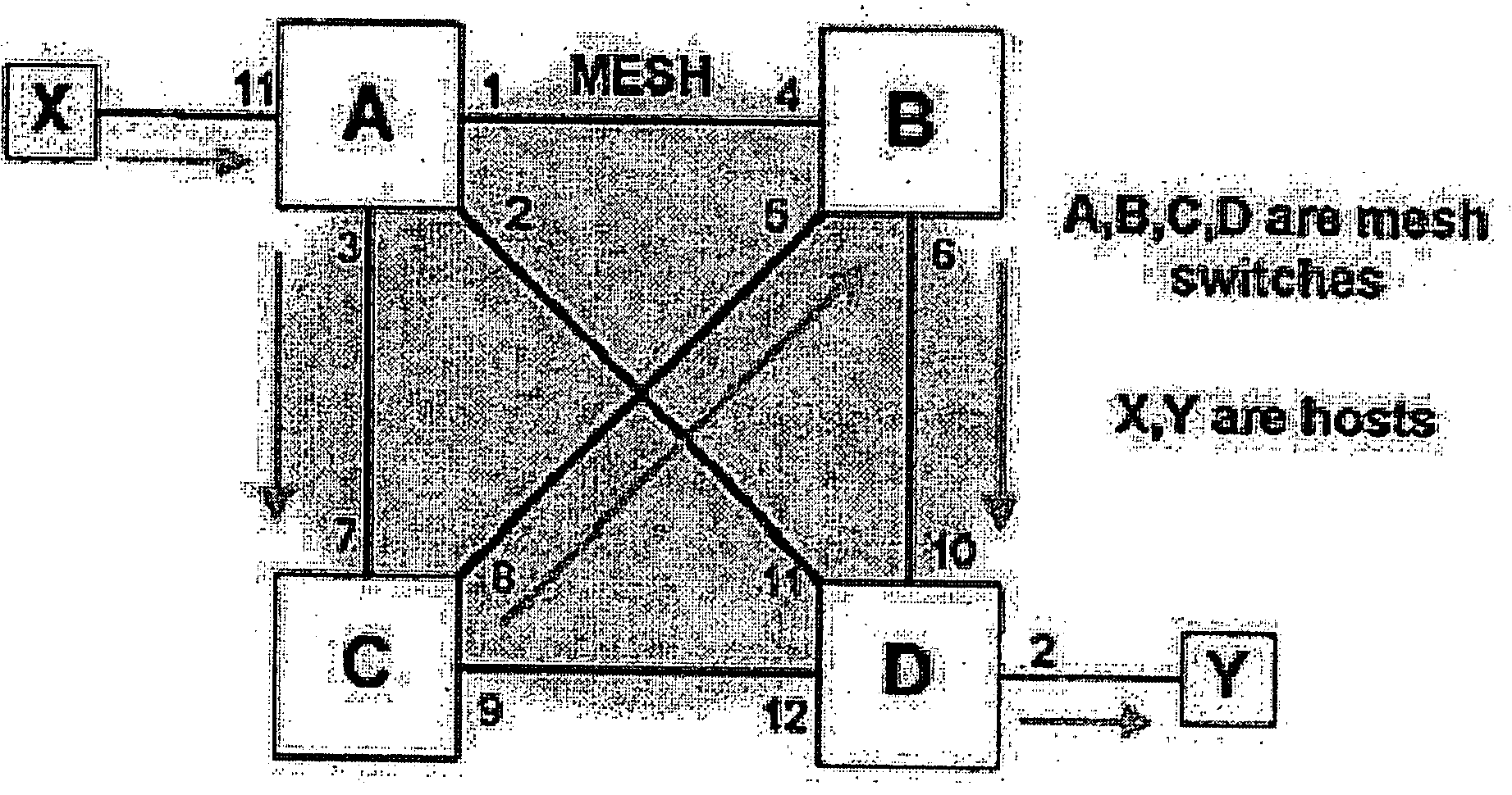
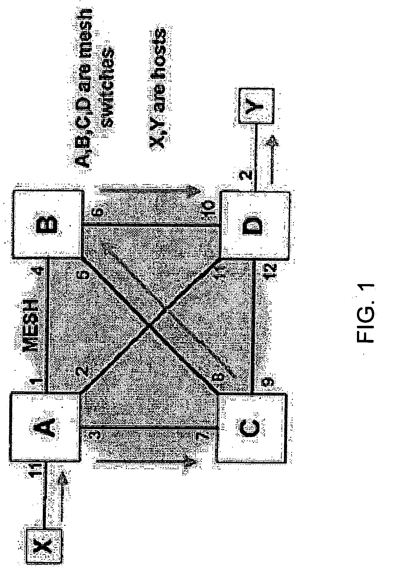
[0028] An embodiment of the present invention overcomes or reduces certain disadvantages of prior mesh-related protocols. As discussed below, determining the path that a packet would take to a given destination within a mesh can be a difficult task. Unlike a normal set of switches, a mesh could have different paths for the addresses learnt from the same switch. To aid in field and in-house debugging, a mesh traceroute protocol is hereby presented that allows a user to quickly determine the path that a packet would take given a destination MAC address and VID.

[0029]FIG. 1 is a schematic diagram depicting a switching mesh. In the example of FIG. 1, the overall switching mesh comprises four interconnected mesh switches (A, B, C, and D). Port 1 of switch A connects to port 4 of switch B. Port 2 of switch A connects to port 11 of switch D. Port 3 of switch A is connected to port 7 of switch C. Port 5 of switch B is connected to port 8 of switch C. And so on.

[0030] In addition, host com...


PUM


Abstract

One embodiment disclosed relates to a method of automated path tracing from an original mesh switch through a switching mesh to a specified destination. A mesh traceroute packet to the specified destination is built. The mesh traceroute packet is transmitted via an exit port associated with the specified destination and the returned packet is received. Another embodiment disclosed relates to a method of responding to receipt of a mesh traceroute packet during an automated path tracing. The mesh traceroute packet is received at a switch. A hop entry is appended to the mesh traceroute packet by the switch.

Description

BACKGROUND OF THE INVENTION [0001] 1. Field of the Invention [0002] The present invention relates generally to communication networks. More specifically, the present invention relates to network switches and diagnostics. [0003] 2. Description of the Background Art [0004] It is common in conventional computing environments to connect a plurality of computing systems and devices through a communication medium often referred to as a network. Such networks among communicating devices permit devices (or users of devices) to easily exchange and share information among the various devices. The Internet is a presently popular example of such networking on a global scale. Individual users attach their computers to the Internet, thereby enabling sharing of vast quantities of data on other computers geographically dispersed throughout the world. [0005] Networked computing systems may be configured and graphically depicted in a wide variety of common topologies. In other words, the particular c...

Claims


Application Information

Patent Timeline
Patent Type & Authority Applications(United States)
IPC IPC(8): H04J1/16H04L12/26H04L12/56
CPCH04L12/2697H04L49/555H04L49/354H04L43/50
Inventor WAKUMOTO, SHAUN KAZUOERSOY, CETIN
Owner HEWLETT-PACKARD ENTERPRISE DEV LP
Why Eureka
Try Eureka