Supercharge Your Innovation With Domain-Expert AI Agents!

Unitized membrane electrode assembly and process for its preparation

Inactive Publication Date: 2005-05-12
EI DU PONT DE NEMOURS & CO
View PDF3 Cites 66 Cited by
  • Summary
  • Abstract
  • Description
  • Claims
  • Application Information

AI Technical Summary

Benefits of technology

[0022] By “prevents contact between the first and second gas diffusion backing layers” is meant that electrical continuity between the first and second coated or uncoated gas diffusion backing layers is effectively blocked.

Problems solved by technology

However, such extension of the membrane often is undesirable since fuel cell coolant may come into contact with its exposed edges and thus cause degradation of the MEA.
Such a construction is difficult to manufacture, however, since care must be taken to avoid inaccuracies in alignment or sizing that could result in gaps between the edges of the annular scrim layer and the edges of the polymer membrane.
Such gaps may cause the gas diffusion backing layers to touch one another, resulting in unwanted electrical pathways.
Furthermore, molten thermoplastic tends to flow sideways during hot pressing, which may cause the membrane border to move away and separate from the scrim layer.
Such separations increase the potential for unwanted electrical pathways.
A disadvantage of having the inner edges coextensive is that lateral flow of the molten thermoplastic beyond the edges of the shim during the hot pressing step causes non-uniformity in the thickness of the seal area in the proximity of the electrochemically active area.

Method used


Image

  • Unitized membrane electrode assembly and process for its preparation
  • Unitized membrane electrode assembly and process for its preparation
  • Unitized membrane electrode assembly and process for its preparation

Examples


example 1

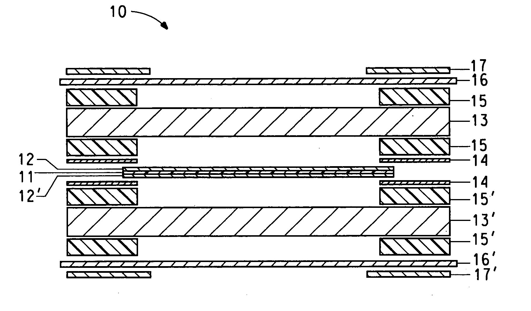
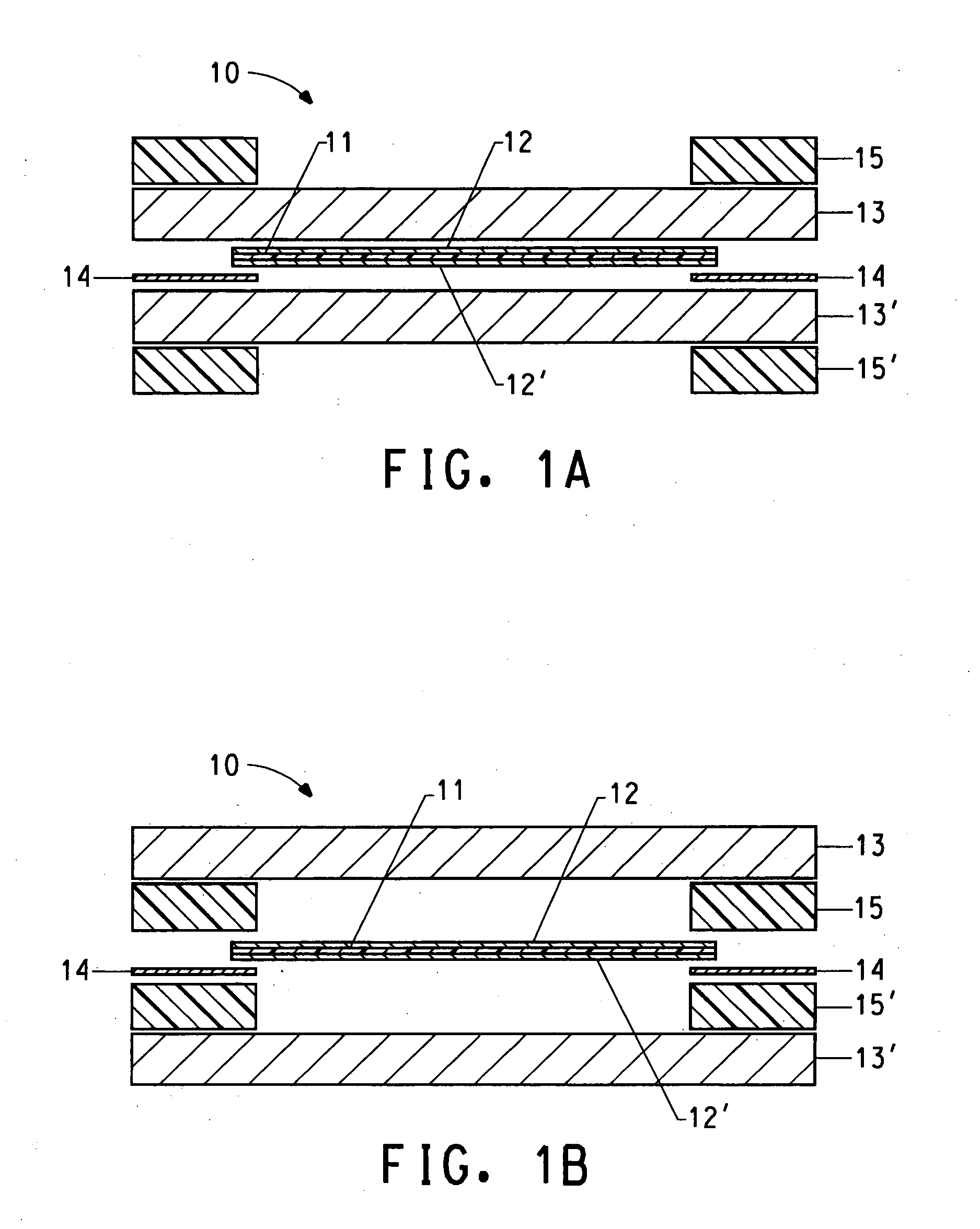
[0091] The following procedure was followed to prepare a unitized MEA: [0092] 1. Two 295 mm×189 mm pieces of gas diffusion backing (carbon fiber based paper, 190 microns thick, 85.5 gm / m2 basis weight, sold as Toray TGP-H-060, available from Toray Composites (America) Inc., Tacoma, Wash.), were cut; [0093] 2. Two picture-framed sealing polymer films (130 micron thick, extruded from linear low density polyethylene resin sold as Bynel® 4105, available from E.I. DuPont de Nemours, Wilmington, Del.) having 295 mm×189 mm outside dimensions and 240 mm×138 mm inside dimensions were cut; [0094] 3. Two picture-framed sealing polymer films having 295 mm×189 mm outside dimensions and 240 mm×138 mm inside dimensions; and a thickness of 60 micron were cut; [0095] 4. One picture-framed insulation layer (para-aramid fiber based paper, 24 gm / m2 basis weight) having 295 mm×189 mm outside dimensions and 240 mm×138 mm inside dimensions); and a thickness of 0.03 mm was cut; [0096] 5. The following laye...

example 2

[0112] The following procedure was followed to prepare a unitized MEA: [0113] 1. Two 420 mm×237 mm pieces of gas diffusion backing (carbon fiber based paper, 415 microns thick, 125 gm / m2 basis weight, sold as Sigracet® GDL 10-BB, available from SGL Technologies, St. Marys, Pa., were cut; [0114] 2. Two picture-framed sealing polymer films (100 micron thick, extruded from linear low density polyethylene resin sold as Bynel® 4105, available from E.I. DuPont de Nemours, Wilmington, Del.) having 416 mm×233 mm outside dimensions and 307 mm×175 mm inside dimensions were cut; [0115] 3. Two picture-framed sealing polymer films having 416 mm×233 mm outside dimensions and 300 mm×175 mm inside dimensions; and a thickness of 75 micron were cut; [0116] 4. Two picture-framed insulation layers (para-aramid fiber based paper, 24 gm / m2 basis weight) having 416 mm×233 mm outside dimensions and 300 mm×175 mm inside dimensions); and a thickness of 0.03 mm were cut; [0117] 5. Two picture-framed shims hav...


PUM

PropertyMeasurementUnit
Lengthaaaaaaaaaa
Pressureaaaaaaaaaa
Densityaaaaaaaaaa

Abstract

The invention provides a unitized membrane electrode assembly having improved edge sealing by a one-step compression molding process.

Description

FIELD OF THE INVENTION [0001] This invention relates to a unitized membrane electrode assembly (“UMEA”) for use in electrochemical cells and more particularly to a unitized membrane electrode assembly wherein the components are electrically isolated from one another using an insulation layer. Further, the invention relates to a one-step compression molding process for preparing unitized membrane electrode assemblies providing high productivity. BACKGROUND OF THE INVENTION [0002] A variety of electrochemical cells falls within a category of cells often referred to as solid polymer electrolyte (“SPE”) cells. An SPE cell typically employs a membrane of a cation exchange polymer that serves as a physical separator between the anode and cathode while also serving as an electrolyte. SPE cells can be operated as electrolytic cells for the production of electrochemical products or they may be operated as fuel cells. [0003] Fuel cells are electrochemical cells that convert reactants, namely ...

Claims


Application Information

Patent Timeline
IPC IPC(8): C25B9/23H01M4/86H01M4/92H01M8/02H01M8/10H01M8/24
CPCC25B9/10Y10T29/4911H01M4/92H01M8/0271H01M8/0273H01M8/0282H01M8/0284H01M8/1004H01M8/1023H01M8/1039H01M8/241H01M8/248H01M2300/0082Y02E60/521Y10T29/49114H01M4/8605Y02E60/50C25B9/23H01M8/242H01M4/86H01M8/02H01M8/10
Inventor BRUNK, DONALD H.PERTI, DEEPAK
Owner EI DU PONT DE NEMOURS & CO
Features
  • R&D
  • Intellectual Property
  • Life Sciences
  • Materials
  • Tech Scout
  • Unparalleled Data Quality
  • Higher Quality Content
  • 60% Fewer Hallucinations
Learn More