Antispasticity aid device and related accessories

an anti-spasticity and hand brace technology, applied in walking aids, physical therapy, medical science, etc., can solve the problem that none of the devices so far developed provides adjustments for the radial orientation of the patient's thumb, and achieve the effect of raising the extension of the arm muscles

Inactive Publication Date: 2005-05-12
FROOM ROBERT K
View PDF24 Cites 8 Cited by
  • Summary
  • Abstract
  • Description
  • Claims
  • Application Information

AI Technical Summary

Benefits of technology

[0041] (30) In another variant, an eighth accessory is provided. The eighth accessory is comprised of a vertically oriented mounting structure. The mounting structure has an upper end, a lower end, a support base located at the lower end and a central adjusting tract. A bearing mount is provided. The bearing mount is slidably affixed to the central adjusting track and has a curved exterior edge. A bearing is provided. The bearing is affixed to a center of the bearing mount. A planar positioning member is provided. The positioning member has a perimeter, a front surface, a rear surface and is affixed to the bearing at a center portion of the rear surface. A planar, L-shaped control bracket is provided. The control bracket is pivotally mounted adjacent to a corner of the L-shape to the front surface of the positioning member adjacent to the perimeter. The control bracket has a control bracket bearing mounted at one end of the L-shape. At least one stop pin is provided. The stop pin is mounted to the front surface of the positioning member and is located between arms of the L-shaped control bracket. An antispasticity aid support member is provided. The support member has an upper surface and a lower surface. The support member is pivotally mounted to the control bracket bearing and is sized and

Problems solved by technology

None of the devices so far developed provide adjust

Method used


Image

  • Antispasticity aid device and related accessories
  • Antispasticity aid device and related accessories
  • Antispasticity aid device and related accessories

Examples


Embodiment Construction

[0084] The present invention addresses all of the deficiencies or prior stroke victim aid inventions and satisfies all of the objectives described above.

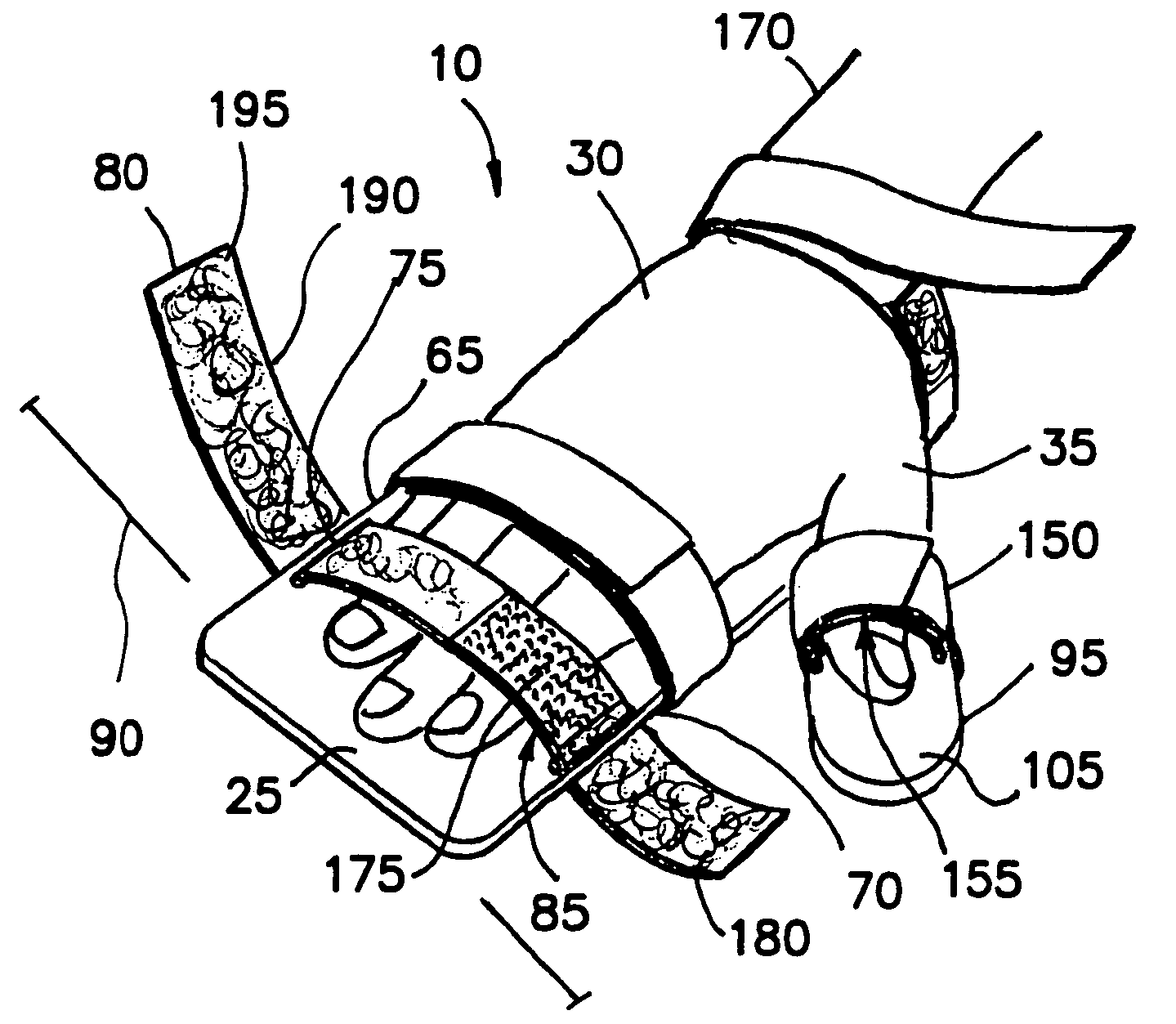
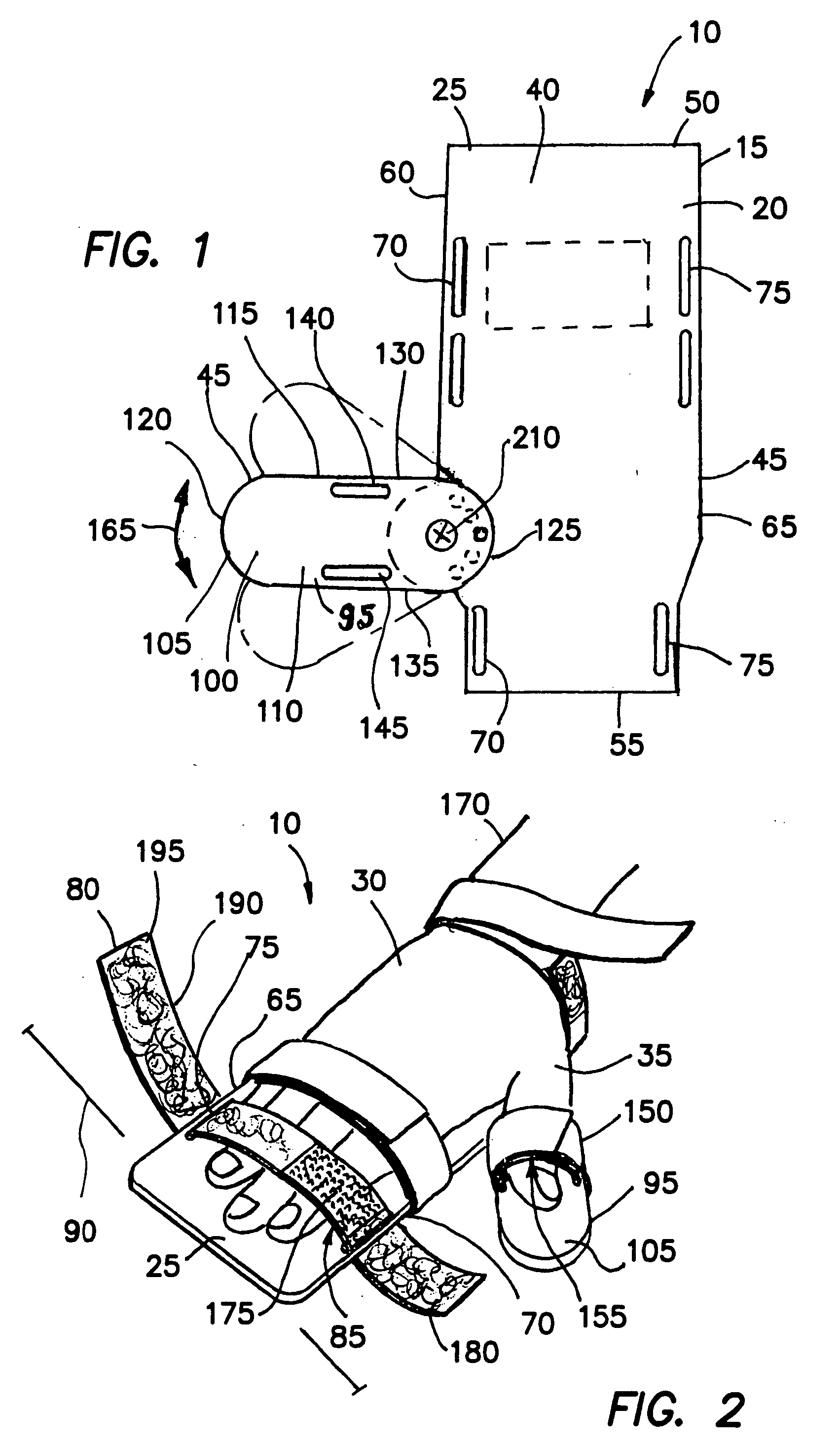
[0085] (1) As shown in FIGS. 1-3, an antispasticity aid device 10 providing the desired features may be constructed from the following components. A planar hand-mounting member 15 is provided. The planar hand-mounting member 15 is formed of rigid material 20 and is sized and shaped to extend beyond the outer dimensions 25 of a human hand 30 without a thumb 35. The planar hand-mounting member 15 has an upper surface 40, a lower surface 45, a front edge 50, a rear edge 55, a first side edge 60 and a second side edge 65. The hand-mounting member 15 has at least two first fastening slots 70, 75 located adjacent to the first 60 and second 65 side edges, respectively. A first restraining strap 80 is provided. The first restraining strap 80 is size and shaped to fit slidably through the first fastening slots 70, 75 and has a means 85 for ...


PUM


Abstract

An antispasticity aid device designed to aid stroke victims. The invention is a hand brace constructed to hold the thumb and fingers flat and a series of accessories designed to re-educate the muscles after a stroke. The device has a hand-mounting and thumb-mounting member. First and second restraining straps hold the hand and thumb firmly in contact with the hand-mounting and thumb-mounting member, respectively. Accessories for use with the device include: A first accessory fitting on an arm of an armchair; a second accessory providing physical therapy; a third accessory maintaining a comfortable position to rest an arm; a fourth accessory fitting frictionally over the arm of a chair; a fifth accessory accepting the mounting bracket of the device; a sixth accessory suspending the arm; a seventh accessory providing a channel for resting an arm; an eighth accessory providing exercise for arm muscles; and a ninth accessory permitting physical therapy.

Description

FIELD OF INVENTION [0001] The invention pertains to devices designed to aid stroke victims and others suffering from spasticity. More particularly, the invention relates to a hand brace constructed to hold the thumb and fingers in a flattened arrangement and a series of devices designed to aid in the re-education of a stroke victim's muscles after a stroke. BACKGROUND OF THE INVENTION [0002] Various devices have been developed to provide comfort and assist in the rehabilitation of those suffering from spasticity of the hand muscles. In order to prevent cramping, nerve damage and possible muscle atrophy, it is often desirable to maintain the patient's hand in a planar orientation. Toward this end, many splint-like devices have been developed. None of the devices so far developed provide adjustments for radial orientation of the patient's thumb. [0003] U.S. Pat. No. 5,121,743 issued to Bishop is directed to a hand-restraining device made of a rigid material. The hand-restraining devic...

Claims


Application Information

Patent Timeline
IPC IPC(8): A61F5/058A61F5/37A61H3/00
CPCA61F5/05866A61H2003/006A61F5/3761
Inventor FROOM, ROBERT K.
Owner FROOM ROBERT K
Why Eureka
Try Eureka