
Trajectory-based video retrieval system, and computer program

a video retrieval and trajectory technology, applied in the field of trajectory-based video retrieval system, can solve the problems of enormous effort to search through video data, increase the amount of stored video data, etc., and achieve the effect of faster retrieval of results and higher priority

Inactive Publication Date: 2014-04-01
ROBERT BOSCH GMBH
View PDF8 Cites 4 Cited by
  • Summary
  • Abstract
  • Description
  • Claims
  • Application Information

AI Technical Summary

Benefits of technology

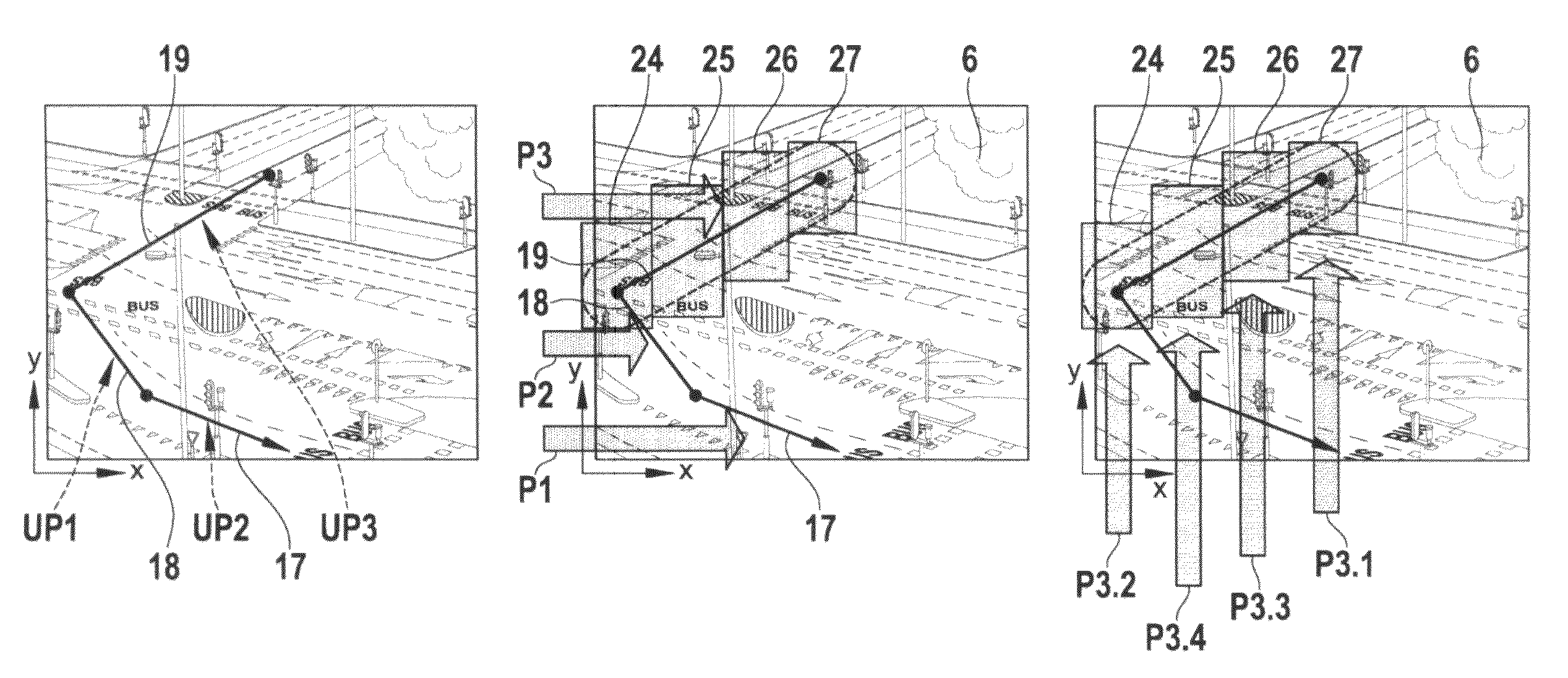
[0011]The underlying idea and the main benefit of the invention is to realize the retrieval means so that the overlap of the minimum bounding areas is minimised. It is most preferred to arrange the areas overlap-free, but for technical reasons in some applications an overlap concerning the borderlines and / or an overlap in general is necessary to improve the programming of the respective algorithm As preferably each minimum bounding area is used as a sub-query, the overall overlap between the plurality of the minimum bounding areas on the one hand side and indexing bounding areas on the other side is minimized and thus the number of double results and consequently the search time is decreased.
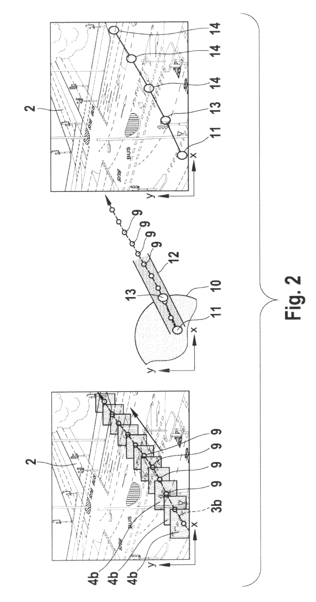
[0016]Further advantages are achievable by an optional embodiment of the invention, wherein the video retrieval system provides ranging means, which is realised for generating a minimum matching range for the single search segment and / or for the search trajectory, whereby the plurality of minimum bounding rectangles are realised to cover the minimum matching range. Preferably the minimum matching range covers the area in a minimum distance from the single search segment and / or from the search trajectory, whereby the minimum distance is preferably defined by the characteristics of the filtering means. In case of a spatial filtering the minimum distance is preferably defined in respect to the maximum or mean distance between two (filtered) interpolating points of the trajectories stored in the database and / or of the search trajectory, especially as half of the maximum distance between two filtered interpolating points. Particularly, the ranging means allows to compensate for negative effects of the filtering means, as the filtering means narrows the spatial extension of the trajectories in the database, thus resulting in a possible loss of matching trajectories. In order to restitute and / or compensate the lost area of the indexing minimum bounding boxes, the ranging means increases artificially the extension of the search trajectory or search segments by generating the minimum matching range.
[0019]In a further embodiment, the prioritising means comprise and / or are connected with input means for setting the priorities manually, especially by a user interaction. Alternatively the prioritising means are realised for setting the priorities automatically, especially dependent on a busyness and / or density table of the search area defined by the search trajectory, search segment or minimum bounding area. Preferably search areas with a higher density of stored trajectories and / or busyness of stored moving objects are allocated to a lower priority level, whereas areas with a lower density are allocated to a higher priority level. The underlying idea is that results from search areas with a lower density and / or busyness allow a faster retrieval of results, so that first results at least concerning the higher prioritised areas are retrieved quickly.
[0020]Further preferred is that the prioritising means allow a combination of manual and automatic prioritisation, whereby preferably in a first step priorities are set manually and in a second step sub-priorities are set automatically (or vice versa) and / or search segments and / or minimum bounding areas without a manually set priority are allocated to a priority automatically. Further a preferably automatically sub-priorisation is possible.

Problems solved by technology

With a growing number of video cameras also the amount of the stored video data is increasing rapidly, which finally results in an enormous effort to search through the video data on- or off-line in case a time instance or location of a certain interesting event is unknown.

Method used


Image

  • Trajectory-based video retrieval system, and computer program
  • Trajectory-based video retrieval system, and computer program
  • Trajectory-based video retrieval system, and computer program

Examples


Embodiment Construction

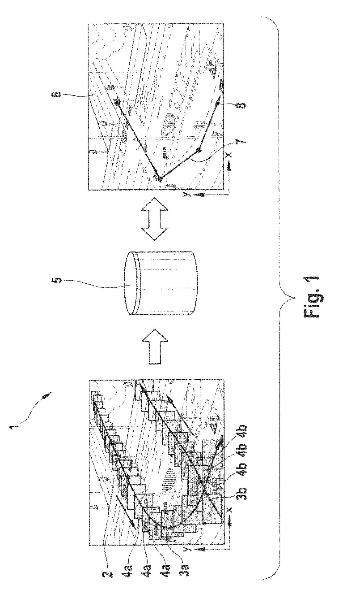
[0032]FIG. 1 shows a schematic overview of the general concept of a video retrieval system 1. On the left hand side of FIG. 1 object tracking is illustrated by means of an image 2 of a traffic crossing with overlaid trajectories 3a and b and object detection windows 4a and 4b. In the image 2 two lines are shown representing two trajectories 3a and b of two different moving objects. The trajectories 3a and b are extracted from a sequence of video frames, whereby in a first step a segmentation and detection algorithm returned the shape and position of each of the moving objects and in a second step each moving object is tracked over its lifetime in the video sequence So the location points of the moving objects in the video frames are used to form the trajectories 3a, b, whereby the trajectories 3a and b are interpolating the centre (or another point) of the object detection windows 4a and 4b respectively, which are object bounding boxes on a frame-by-frame basis. These trajectories 3...


PUM


Abstract

A video retrieval system is proposed that retrieves trajectory data from a database as a response to a search query. The search query is formulated on the basis of a search trajectory, which is represented as a plurality of search segments. Minimum hounding areas are generated, whereby the plurality of the minimum hounding areas cover the search trajectory or at least one of the search segments. The video retrieval system accesses the database by using at least one of the minimum bounding areas as a query area, whereby the minimum bounding areas of the plurality of bounding areas are arranged overlap-free and / or adjacently or with a search trajectory independent overlap.

Description

CROSS-REFERENCE[0001]The invention described and claimed hereinbelow is also described in PCT / EP2006 / 060300, filed on Feb. 27, 2006. This patent application, whose subject matter is incorporated here by reference, provides the basis for a claim of priority of invention under 35 U.S.C. 119 (a)-(d).BACKGROUND OF THE INVENTION[0002]The invention relates to a video retrieval system for retrieving video data. More specifically the invention relates to a video retrieval system with a retrieval means for retrieving trajectory data from a database as a response to a search query, whereby the search query is formulated on the basis of a search trajectory, which is representable and / or represented as a plurality of search segments, whereby the retrieval means comprises interpreting means for generating a plurality of minimum bounding areas, whereby the plurality of the minimum bounding areas covers the search trajectory or at least one of the search segments and whereby the retrieval means is...

Claims


Application Information

Patent Timeline
Patent Type & Authority Patents(United States)
IPC IPC(8): G06F17/30
CPCG06F17/30831G06F17/30811G06F16/786G06F16/7335
Inventor ALBERS, ROBJASPERS, EGBERTWIJNHOVEN, ROB
Owner ROBERT BOSCH GMBH
Learn More