Electromagnetic actuator

a technology of electromagnetic actuators and actuators, which is applied in the direction of electromagnets with armatures, dynamo-electric components, dynamo-electric machines, etc., can solve the problems of limited stroke of electromagnetic actuators and inability to obtain large strokes, and achieve the effect of increasing thrus

Inactive Publication Date: 2005-05-19
SMC CORP
View PDF9 Cites 37 Cited by
  • Summary
  • Abstract
  • Description
  • Claims
  • Application Information

AI Technical Summary

Benefits of technology

[0013] An electromagnetic actuator according to the present invention can obtain a larger thrust, by combining a permanent magnet and a core for forming a moving object, than that of a conventional electromagnetic actuator in which a moving object is formed only with a permanent magnet.

Problems solved by technology

Generally, this kind of electromagnetic actuator has a limited stroke, and cannot obtain a large stroke unlike a rotary motor.

Method used


Image

  • Electromagnetic actuator
  • Electromagnetic actuator
  • Electromagnetic actuator

Examples


first embodiment

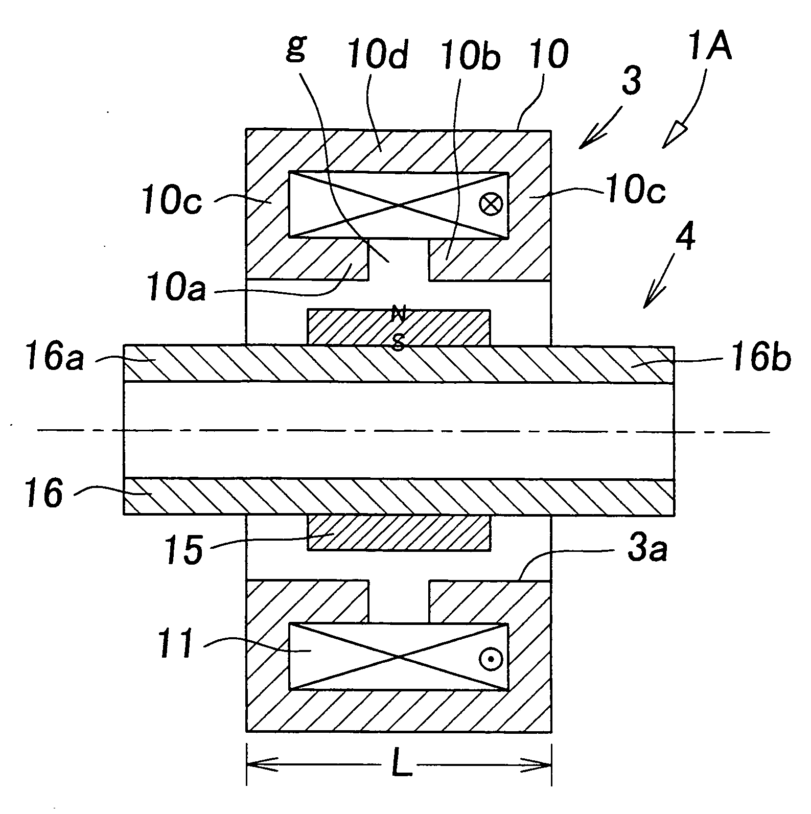
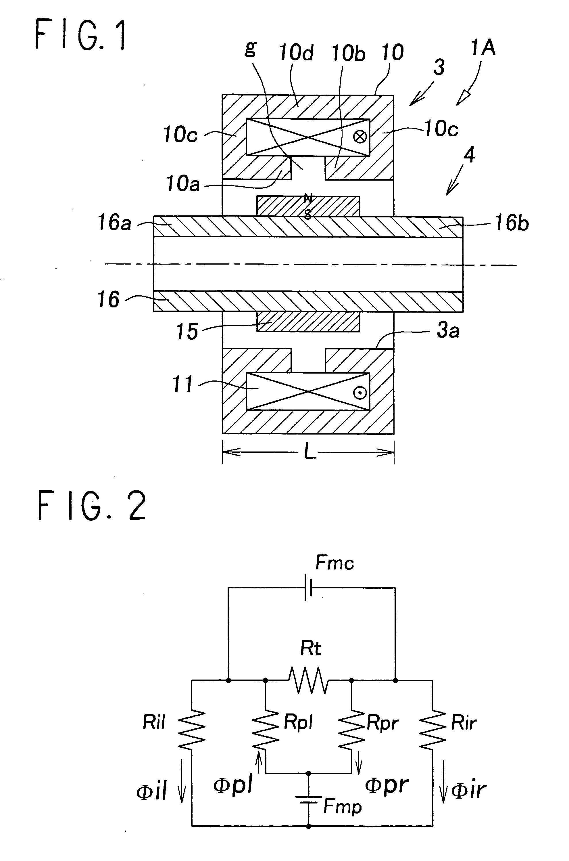
[0026]FIG. 1 shows a principle of an electromagnetic actuator according to the present invention. The electromagnetic actuator 1A comprises a cylindrical electromagnet 3; and a moving object 4 which is movably fitted into a center hole 3a of the electromagnet 3 in the direction of the axis line.

[0027] The electromagnet 3 includes a fixed core 10 of a magnetic material, and one set of exciting coils 11 wound on the fixed core 10. The fixed core 10 comprises: one pair of a first pole tooth 10a and a second pole tooth 10 b, which are cylindrical and coaxially face each other through a gap g; flange-type side wall sections 10c and 10c, which extend to the outer peripheral side from the rear end section of each of the pole teeth 10a, 10b; and a cylindrical principal wall section 10d which combines the side wall sections 10c and 10c together at their outer peripheral edge, and the coil 11 is contained inside of the fixed core 10 so that the coil 11 surrounds the outer peripheries of the p...

second embodiment

[0061]FIG. 7 shows an electromagnetic actuator according to the present invention. In the electromagnetic actuator 1B, a concave groove 16c in the circumferential direction is formed so that the groove 16c faces pole teeth 10a and 10b on the surface of the outer periphery of a movable core 16, and a permanent magnet 15 is fitted into and fixed in the concave groove 16c. Though the outer diameter of the permanent magnet 15 may be larger than that of the movable core 16, the diameter is formed to be almost equal to that of the movable core 16 in the shown example. Accordingly, the surface of the outer periphery of the permanent magnet 15, and that of the outer peripheries of a first core section 16a and a second core section 16b of the movable core 16 are located substantially on the same circumferential surface.

[0062] As other portions of the second embodiment are substantially the same as those of the first embodiment, the same reference numerals as those in the first embodiment are...


PUM

PropertyMeasurementUnit
axial lengthsaaaaaaaaaa
axial lengthaaaaaaaaaa
lengthaaaaaaaaaa

Abstract

An electromagnetic actuator comprises: a fixed core of a magnetic material provided with one pair of pole teeth, which are cylindrical and face each other; exciting coils wound on the fixed core; and a moving object which is movably disposed in the direction of the axis line coaxially with the pole teeth, wherein the moving object includes: cylindrical permanent magnet, in which the N pole and the S pole have been magnetized in the radial direction; and a cylindrical movable core of magnetic material which is coaxially connected to the permanent magnet and is displaced together with the permanent magnet.

Description

TECHNICAL FIELD [0001] The present invention relates to an electromagnetic actuator which drives a moving object in a straight line, using a magnetic force generated at application of direct voltage. BACKGROUND ART [0002] Such a linear electromagnetic actuator which drives a moving object in a straight line, using a magnetic force generated at application of direct voltage, has been known as, for example, VCM, a solenoid, and the like so far. Generally, this kind of electromagnetic actuator has a limited stroke, and cannot obtain a large stroke unlike a rotary motor. The reason is that the larger stroke causes more reduced thrust. [0003] On the other hand, an electromagnetic actuator using a permanent magnet as a moving object has been disclosed in Japanese Patent Application Laid-open No. 7-94323 (JP-A) and JP-A No. 2002-101631. When a permanent magnet is used as a moving object like the above actuator, the actuator can generate a larger thrust with low voltage than that of an actu...

Claims


Application Information

Patent Timeline
Patent Type & Authority Applications(United States)
IPC IPC(8): H01F7/06H01F7/16H02K33/16H02K41/00H02K41/03
CPCH02K41/03H02K33/16
Inventor YAJIMA, HISASHIFUJIWARA, NOBUHIRO
Owner SMC CORP
Why Eureka
Try Eureka