Magnetic resonance imaging array coil system and method for breast imaging

a magnetic resonance imaging and array coil technology, applied in the field of magnetic resonance imaging array coil systems, can solve the problems of reduced snr, limited sense capability of known coils dedicated to breast mri, and limited coverag

Active Publication Date: 2005-05-19
GENERAL ELECTRIC CO
View PDF8 Cites 45 Cited by
  • Summary
  • Abstract
  • Description
  • Claims
  • Application Information

AI Technical Summary

Problems solved by technology

Known coils dedicated to breast MRI have very limited SENSE capability, if any at all, limited coverage, reduced SNR, more complex designs or decoupling arrangements, and/or are configured having a closed coil geometry that is

Method used


Image

  • Magnetic resonance imaging array coil system and method for breast imaging
  • Magnetic resonance imaging array coil system and method for breast imaging
  • Magnetic resonance imaging array coil system and method for breast imaging

Examples


Embodiment Construction

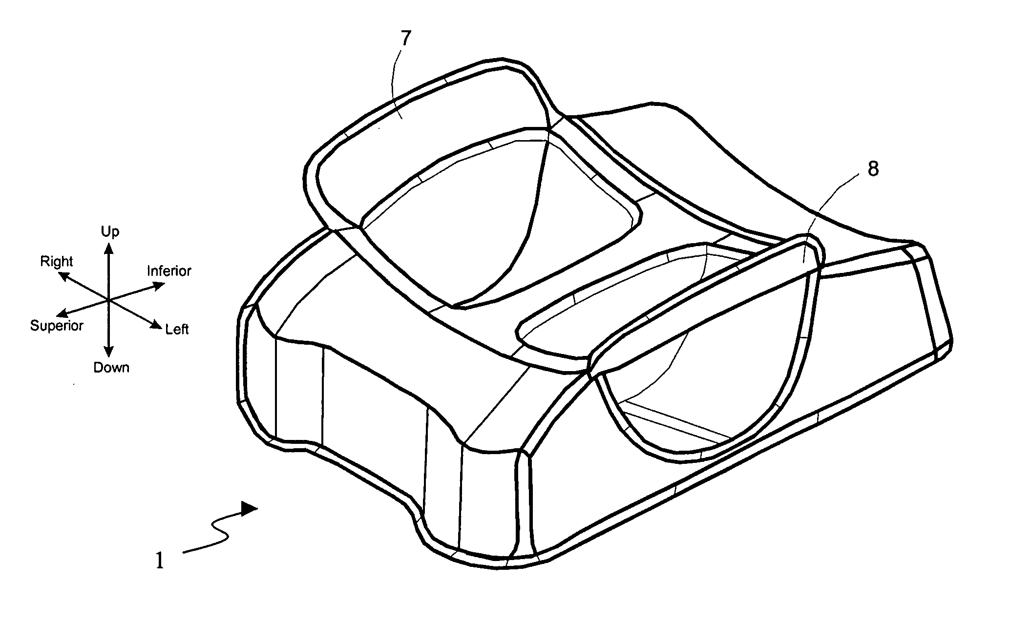
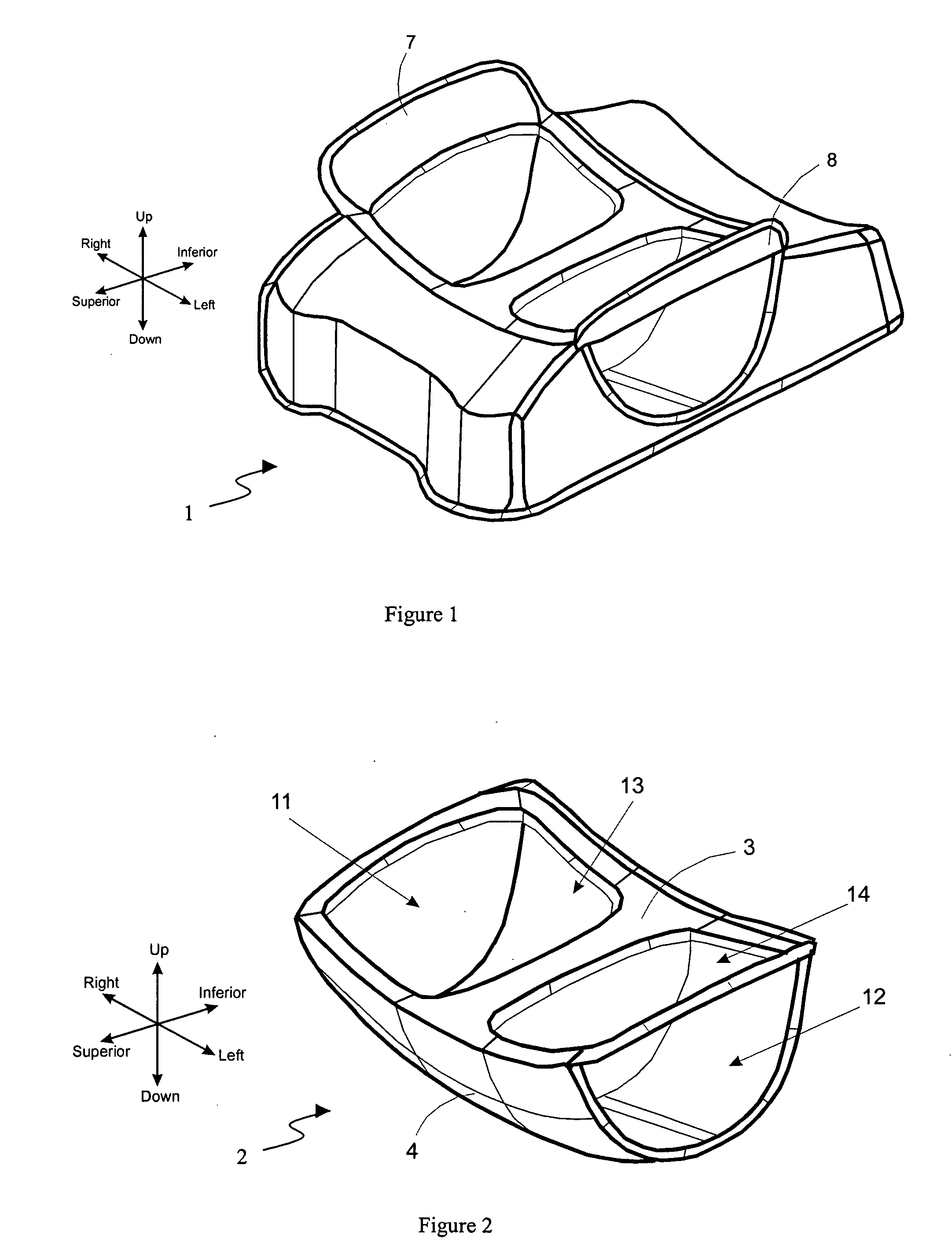
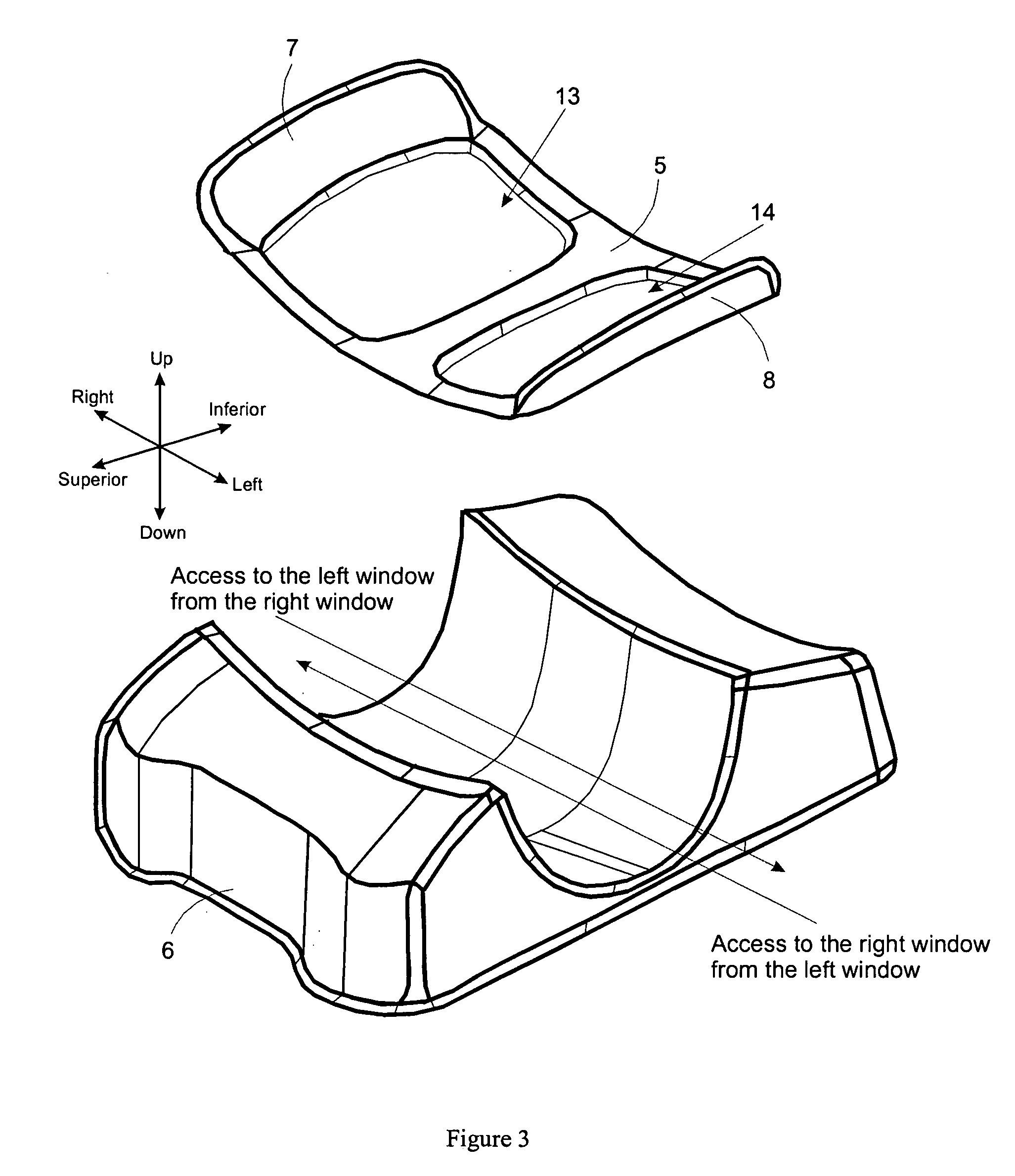
[0034]FIG. 1 shows an MRI array coil system 1 constructed in accordance with one embodiment of the present invention. The MRI array coil system 1 generally includes a main coil chamber 2, a main bottom coil housing 6, a right wing 7 and a left wing 8. The main coil chamber 2, as shown in FIG. 2, is formed by a top coil portion, for example, a top coil plate 3 and a bottom coil portion, for example, a bottom coil former 4. The top coil plate 3 and the bottom coil former 4 are fixedly (e.g., permanently) connected in this embodiment. A right opening 13 and a left opening 14 are provided on the top coil plate 3 to receive the imaged objects (e.g., the left and right breasts of a human). The ends of the main coil chamber 2 also are open forming two windows 11 (right window) and 12 (left window), to allow access from both ends of the main coil chamber 2. Two wings 7 and 8 may be provided on rigid or semi-flexible formers that may be attached to the two ends of the top coil plate 3 as sho...


PUM


Abstract

A magnetic resonance imaging (MRI) array coil system and method for breast imaging are provided. The MRI array coil system includes a top coil portion with two openings configured to receive therethrough objects to be imaged. The MRI array coil system further includes a bottom coil portion having two openings configured to access from sides of the bottom coil portion the objects to be imaged. The top coil portion and bottom coil portion each have a plurality of coil elements configured to provide parallel imaging.

Description

CROSS REFERENCE TO RELATED APPLICATIONS [0001] This application claims priority to and the benefit of the filing date of U.S. Provisional Application No. 60 / 523,456 filed on Nov. 19, 2003 and which is hereby incorporated by reference in its entirety.BACKGROUND OF THE INVENTION [0002] This invention relates generally to Magnetic Resonance Imaging (MRI) systems, and more particularly, to Radio-Frequency (RF) coils in MRI systems. [0003] In MRI, the RF receive coil is one of the most important hardware components in the imaging system. A special-purpose receive coil for a region of interest is typically used for reception to enhance the signal-to-noise ratio (SNR) at that region. [0004] For RF receive coils, it is known to further increase SNR using quadrature reception. In quadrature reception, NMR signals are detected in two orthogonal directions, which are in the transverse plane or perpendicular to the main magnetic field. The two signals are detected by two independent individual ...

Claims


Application Information

Patent Timeline
IPC IPC(8): G01R33/3415
CPCG01R33/3415
Inventor QU, KUNCHAN, PEI H.ZHENG, TSINGHUAMURPHY-BOESCH, JOSEPHPETROPOULOS, LABROS S.
Owner GENERAL ELECTRIC CO
Why Eureka
Try Eureka