Coil arrays for parallel imaging in magnetic resonance imaging

a parallel imaging and magnetic resonance imaging technology, applied in the field of magnetic resonance imaging (mri) systems, can solve the problems of low signal-to-noise ratio (snr or s/n), large coils, and poor imaging depth tissue imaging performance of coil systems, and achieve the trade-off between basic noise and geometry factor

Active Publication Date: 2007-05-22
GENERAL ELECTRIC CO
View PDF12 Cites 29 Cited by
  • Summary
  • Abstract
  • Description
  • Claims
  • Application Information

AI Technical Summary

Problems solved by technology

A large coil, however, produces lower signal-to-noise ratio (SNR or S / N) if it is also used for reception, mainly because of its greater distance from the signal-generating tissues being imaged.
However, these coil systems do not operate well for imaging deep tissues, such as, for example, the blood vessels in the lower abdomen, due to the sensitivity drop-off away from the coil surface.
For SENSE imaging, the elements of a coil array may be smaller than for common multi-array imaging, resulting in a trade-off between basic noise and geometry factor.
Some known PPA coil arrays are based upon traditional RF coil design requirements using conventional coil design schemes and thus have the limitations of conventional systems (e.g., increased acquisition time).
Thus, these known PPA coil arrays are not optimized for parallel imaging operation and limit the design options for such arrays.
Therefore, the operation and control of an associated MRI system, operating, for example, using SENSE or SMASH is limited when using these known coil arrays.

Method used


Image

  • Coil arrays for parallel imaging in magnetic resonance imaging
  • Coil arrays for parallel imaging in magnetic resonance imaging
  • Coil arrays for parallel imaging in magnetic resonance imaging

Examples


Embodiment Construction

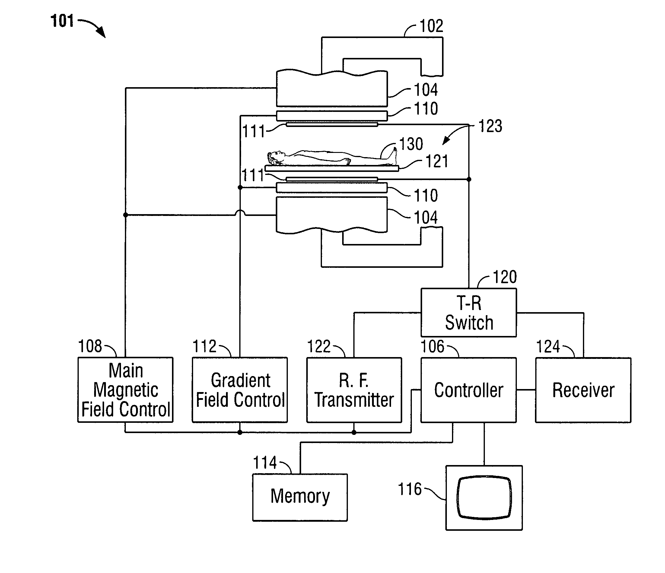
[0025]Various exemplary embodiments of the present invention provide a system and method for parallel imaging, such as partial parallel imaging or partial parallel acquisition (PPA), and more particularly, coil arrangements for use in a magnetic resonance imaging (MRI) system to provide parallel imaging. For example, the various exemplary embodiments provide coil arrays optimized for operation in PPA. The coil arrays of the various embodiments provide improved volume and surface array coils that cover a large field-of-view (FOV) while providing greater SNR. The coil arrays can be used, for example, as a PPA targeted coil for imaging a large volume such as a head, abdomen, torso or heart. Further, and for example, the coil arrays provide better SNR, for example, for torso and cardiac imaging using PPA.

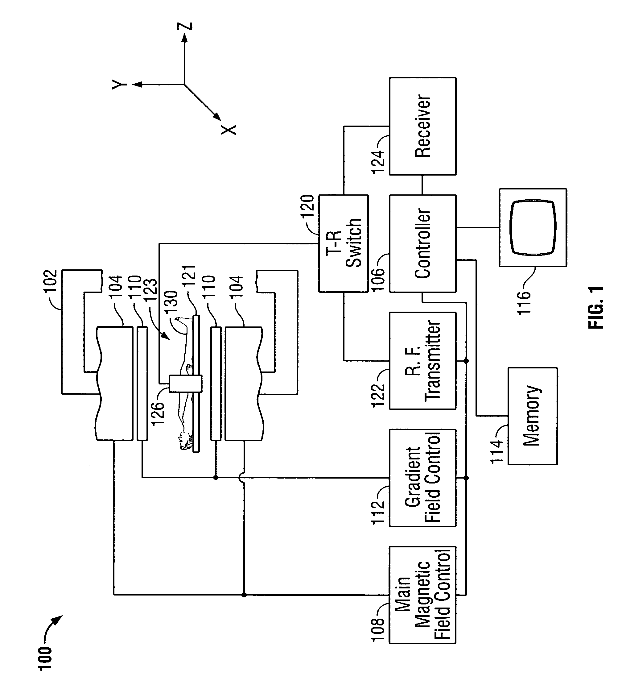
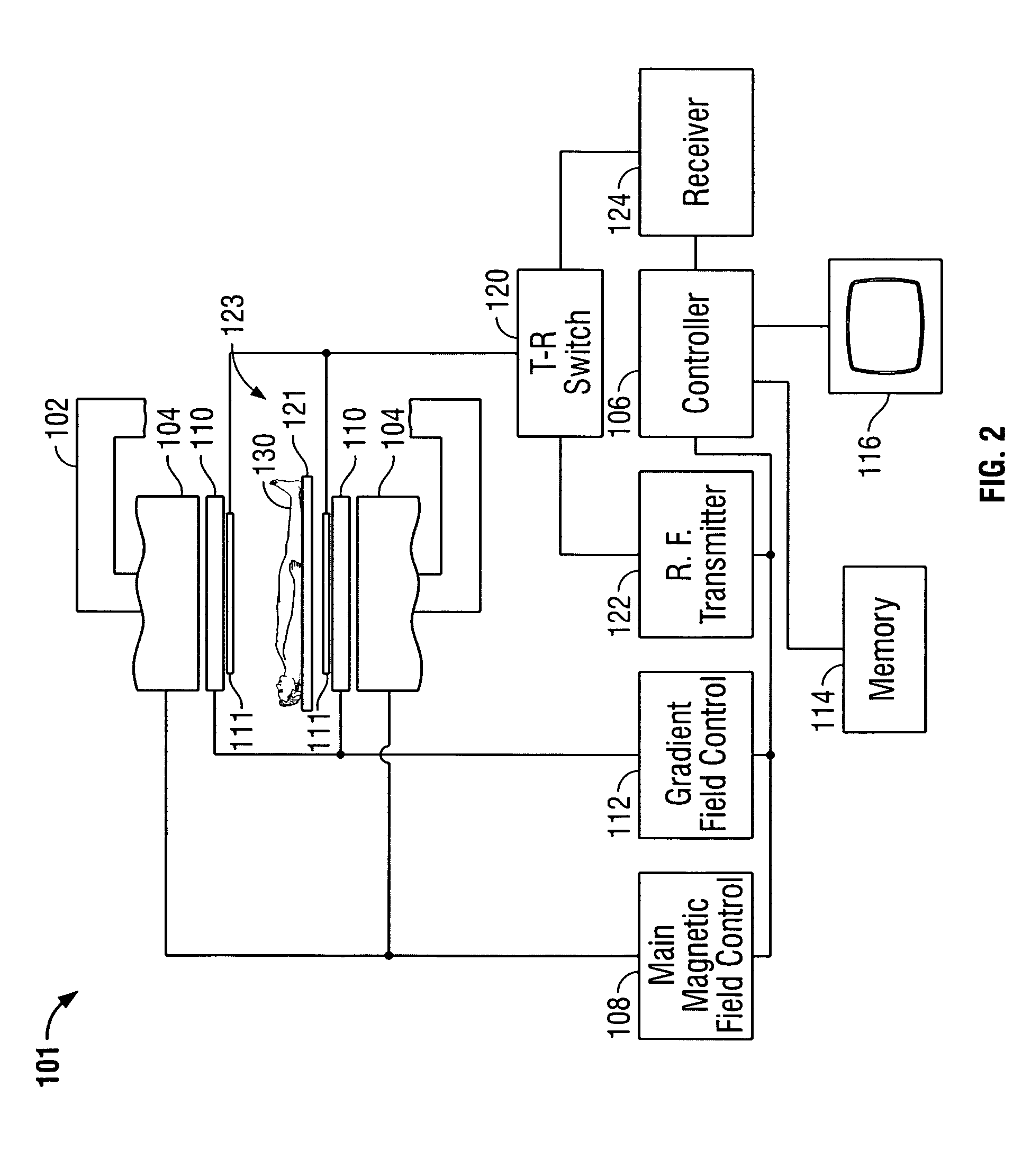
[0026]FIG. 1 is a block diagram of an exemplary embodiment of an MRI system in which systems and methods for decoupling in accordance with various embodiments of the present invention m...


PUM


Abstract

A system and method for configuring coils in a coil array are provided. The system includes a coil arrangement for a medical imaging system. The coil arrangement includes a plurality of coil elements for a medical imaging system and a plurality of twisted portions in combination with at least one of the plurality of coil elements.

Description

CROSS REFERENCE TO RELATED APPLICATIONS[0001]This application claims priority to and the benefit of the filing date of U.S. Provisional Application No. 60 / 441,518, filed on Jan. 21, 2003 and which is hereby incorporated by reference in its entirety.BACKGROUND OF THE INVENTION[0002]This invention relates generally to magnetic resonance imaging (MRI) systems and, more particularly, to radio-frequency (RF) coils in such systems.[0003]Magnetic Resonance Imaging (MRI) utilizes hydrogen nuclear spins of the water molecules in the human body, which are polarized by a strong, uniform, static magnetic field generated by a magnet (typically denoted as B0—the main magnetic field in MRI physics). The magnetically polarized nuclear spins generate magnetic moments in the human body. The magnetic moments point or are aligned parallel to the direction of the main magnetic field B0 in a steady state and produce no useful information if they are not disturbed by any excitation.[0004]The generation of...

Claims


Application Information

Patent Timeline
Patent Type & Authority Patents(United States)
IPC IPC(8): G01V3/00G01R33/3415
CPCG01R33/3415
Inventor FUJITA, HIROYUKIZOU, MARK XUEMINGSPENCE, DAN K.
Owner GENERAL ELECTRIC CO
Why Eureka
Try Eureka