Imaging fluorescence signals using telecentric optics

a fluorescence signal and optics technology, applied in the field of dna analysis, can solve the problems of difficult to meet the requirements of fluorescence reading devices, limited size and lateral density of individual sites, and difficult illumination of the whole support, etc., and achieve the effect of accurate imaging of the corresponding fluorescence signals

Active Publication Date: 2010-03-30
ROCHE DIAGNOSTICS OPERATIONS INC
View PDF36 Cites 29 Cited by
  • Summary
  • Abstract
  • Description
  • Claims
  • Application Information

AI Technical Summary

Problems solved by technology

One major problem of all fluorescence reading devices is the enormous intensity of the excitation light in comparison with the fluorescence light emitted by the dye and therefore, one has to assure that the excitation beam does not hit the detector in order to monitor the fluorescence signals accurately.
However, if more than one fluorescence label is present in the sample, a lateral distribution of spots on a solid support or the fluorescence of a microtiter plate has to be monitored, the requirements for the fluorescence reading device are more difficult to fulfill.
The scanning strategy has the obvious drawback that either the support has to be moved in two dimensions (WO 03 / 069391, DE 102 00 499) or the detector has to be moved with respect to the support (US 2002 / 159057).
On the other hand, the main difficulty of the strategy to illuminate the whole support simultaneously is to assure a homogeneous illumination across the whole distribution of sites.
Due to the necessity of an array of vial lenses, the size and the lateral density of individual sites is limited.

Method used


Image

  • Imaging fluorescence signals using telecentric optics
  • Imaging fluorescence signals using telecentric optics
  • Imaging fluorescence signals using telecentric optics

Examples


example

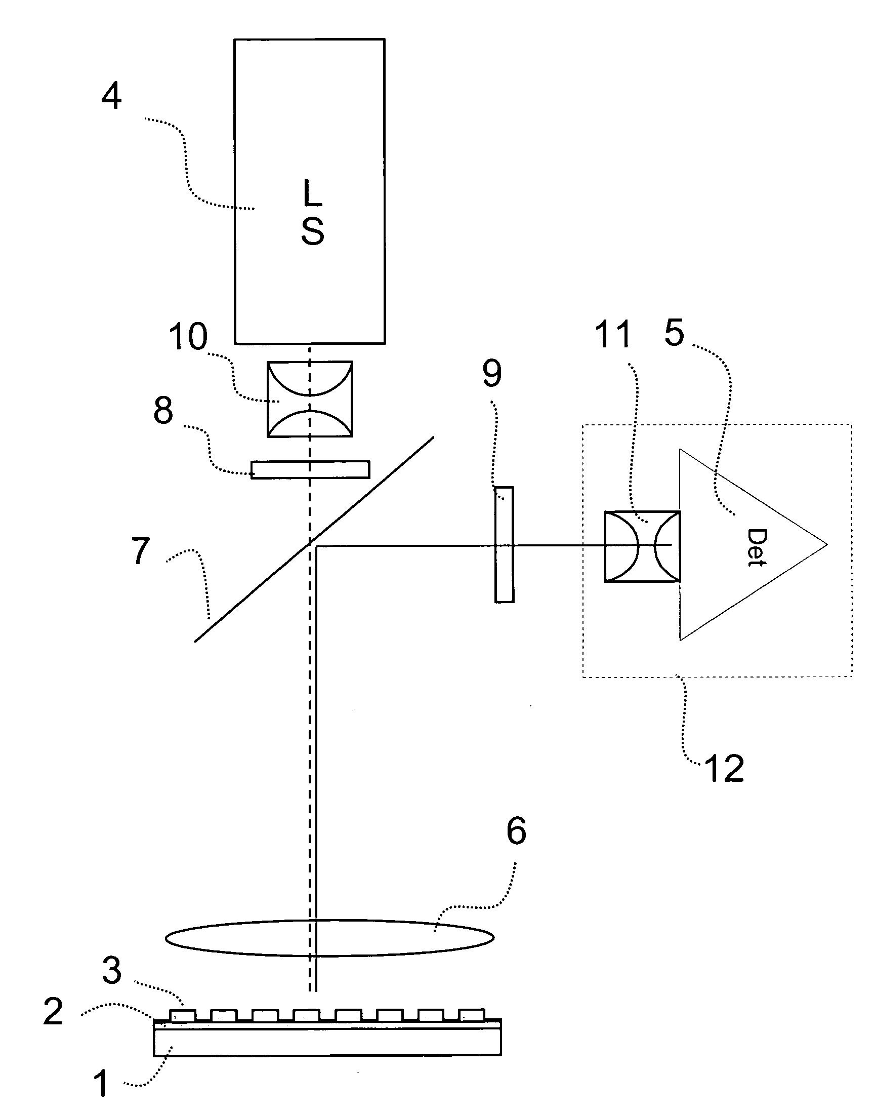
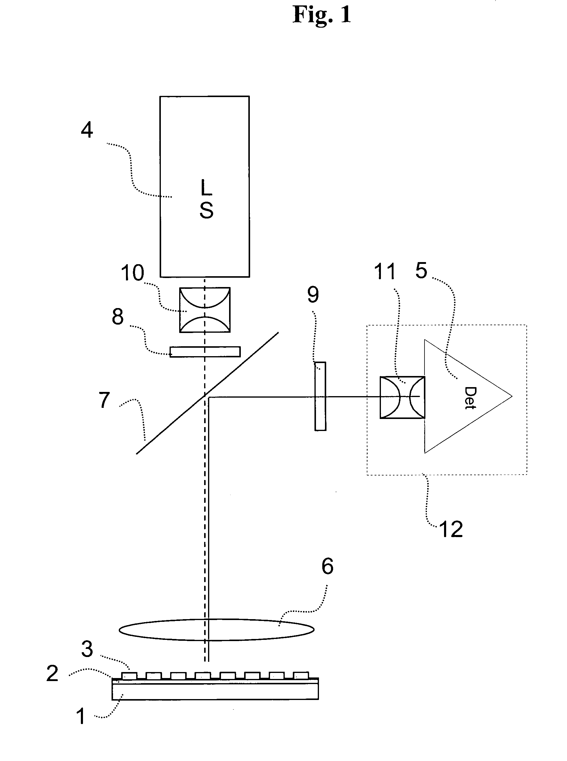
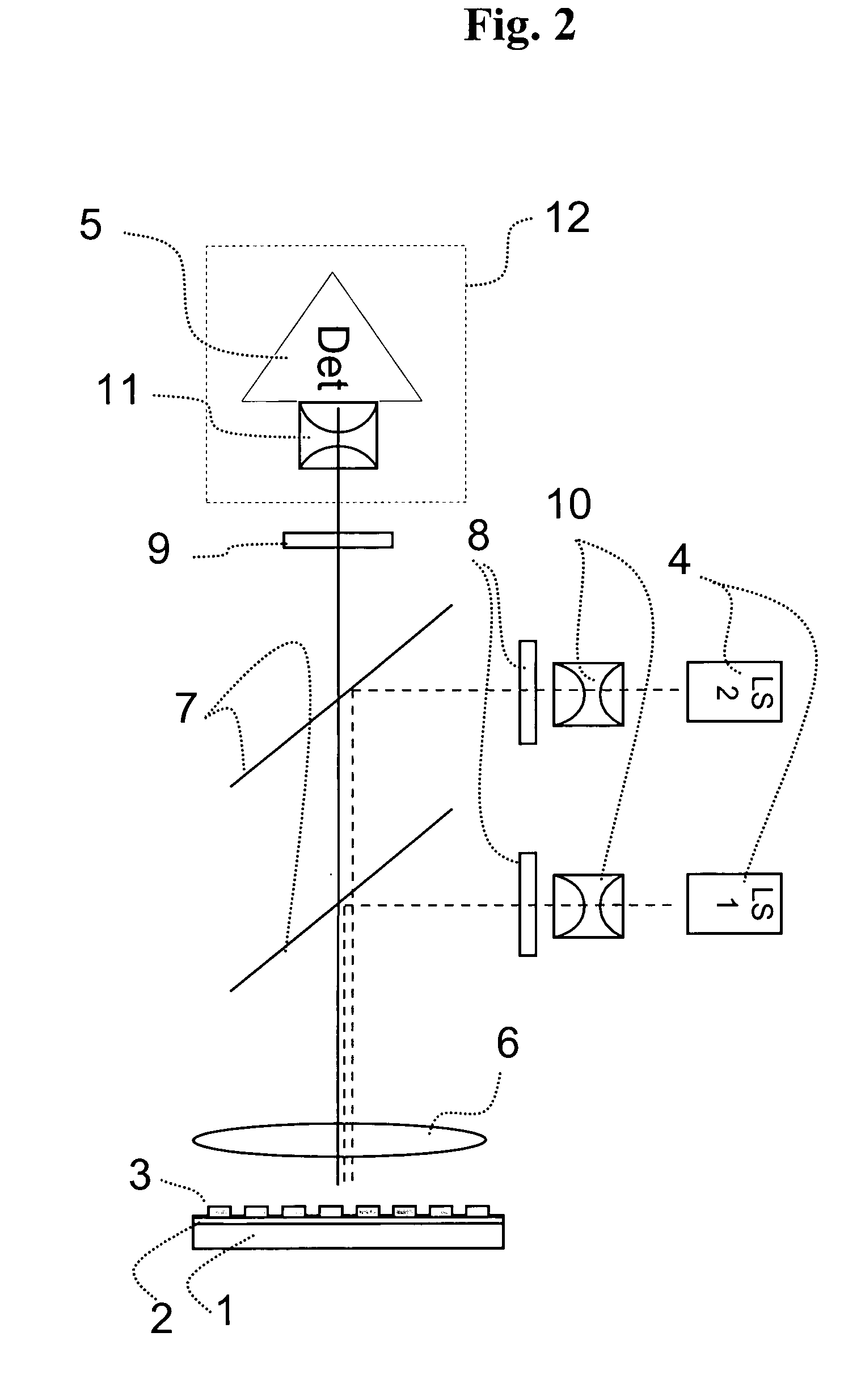
[0139]An optical instrument as explained in the detailed description and as illustrated in FIG. 2 (with only one light source) was configured as follows. The telecentric excitation optic was adjusted to handle frequencies from 450 to 650 nm and the telecentric imaging optic to handle frequencies from 500 to 740 nm. The light source was a Xenon lamp and as transducer a cooled ⅔″ CCD chip with 1024×1344 pixels was used. The optical instrument was designed to image an area of 83 mm×117 mm so that microtiter plates (MTP) with 96 wells (distance 9 mm; diameter 5 mm) and 384 (distance 4.5 mm; diameter 3 mm) can be used. The appropriate wavelength for excitation and imaging for certain fluorescence dyes was adjusted by filter wheels.

[0140]The telecentric excitation optic had a numerical aperture on the side of the light source of 0.35 and on the side of the MTP of 0.014. The light source was arranged perpendicular to the CCD chip and the excitation light beam had to be oriented towards the...


PUM

PropertyMeasurementUnit
angle of incidenceaaaaaaaaaa
distanceaaaaaaaaaa
field depthaaaaaaaaaa

Abstract

The present invention relates to the field of DNA analysis. In particular, the present invention is directed to a device for the parallel imaging of fluorescence intensities at a plurality of sites as a measure for DNA hybridization. More particular, the present invention is directed to a device to image multiplex real time PCR or to read out DNA microarrays.

Description

RELATED APPLICATIONS[0001]This application claims priority to European patent application EP 05000862.2 filed Jan. 18, 2005.FIELD OF THE INVENTION[0002]The present invention relates to the field of DNA analysis. In particular, the present invention is directed to a device for the parallel imaging of fluorescence intensities at a plurality of sites.BACKGROUND OF THE INVENTION[0003]Various applications of fluorescence techniques to analyze biological samples are known to people skilled in the art. In case of electrophoretic techniques proteins or DNA are labeled with a fluorescence probe to visualize their electrophoretic bands in gels or columns. In addition, most biochip applications so far are based on a fluorescence read-out, whereas the specific binding of a fluorescence-labeled target molecule to a probe molecule immobilized on a solid support is monitored. Applications for DNA analysis in the liquid phase include fluorescence hybridization probes like the double-stranded DNA bi...

Claims


Application Information

Patent Timeline
Patent Type & Authority Patents(United States)
IPC IPC(8): C12M1/34C12M3/00
CPCG01N21/6452G01N21/6456G01N21/6458G01N35/028G01N2021/6478G01N2035/00158
Inventor GUTEKUNST, MARTIN
Owner ROCHE DIAGNOSTICS OPERATIONS INC
Why Eureka
Try Eureka