Imaging fluorescence signals using telecentricity

a fluorescence signal and telecentric technology, applied in the field of dna analysis, can solve the problems of difficult to meet the requirements of the fluorescence reading device, limited size and lateral density of individual sites, and difficult illumination of the whole support, etc., and achieve the effect of accurate imaging of the corresponding fluorescence signals

Active Publication Date: 2006-08-31
ROCHE DIAGNOSTICS OPERATIONS INC
View PDF46 Cites 21 Cited by
  • Summary
  • Abstract
  • Description
  • Claims
  • Application Information

AI Technical Summary

Benefits of technology

[0009] Thus, the invention is directed to an optical instrument to image the fluorescence of an assembly of multiple individual sites, comprising a homogeneous excitation across the whole assembly area as well as an accurate imaging of the corresponding fluorescence signals.

Problems solved by technology

One major problem of all fluorescence reading devices is the enormous intensity of the excitation light in comparison with the fluorescence light emitted by the dye and therefore, one has to assure that the excitation beam does not hit the detector in order to monitor the fluorescence signals accurately.
However, if more than one fluorescence label is present in the sample, a lateral distribution of spots on a solid support or the fluorescence of a microtiter plate has to be monitored, the requirements for the fluorescence reading device are more difficult to fulfill.
The scanning strategy has the obvious drawback that either the support has to be moved in two dimensions (WO 03 / 069391, DE 102 00 499), the detector has to be moved with respect to the support (US 2002 / 159057), the detector has to move in one dimension and the support in the other dimension or the optics has to include one or two dimensional scanning means i.e. galvo mirrors.
On the other hand, the main difficulty of the strategy to illuminate the whole support simultaneously is to assure a homogeneous illumination across the whole distribution of sites.
Due to the necessity of an array of vial lenses, the size and the lateral density of individual sites is limited.

Method used


Image

  • Imaging fluorescence signals using telecentricity
  • Imaging fluorescence signals using telecentricity
  • Imaging fluorescence signals using telecentricity

Examples


specific embodiments

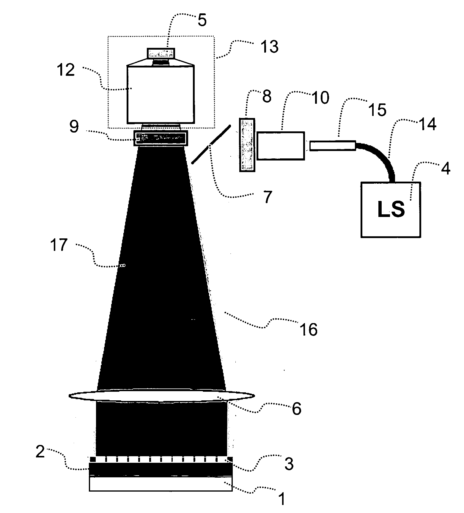
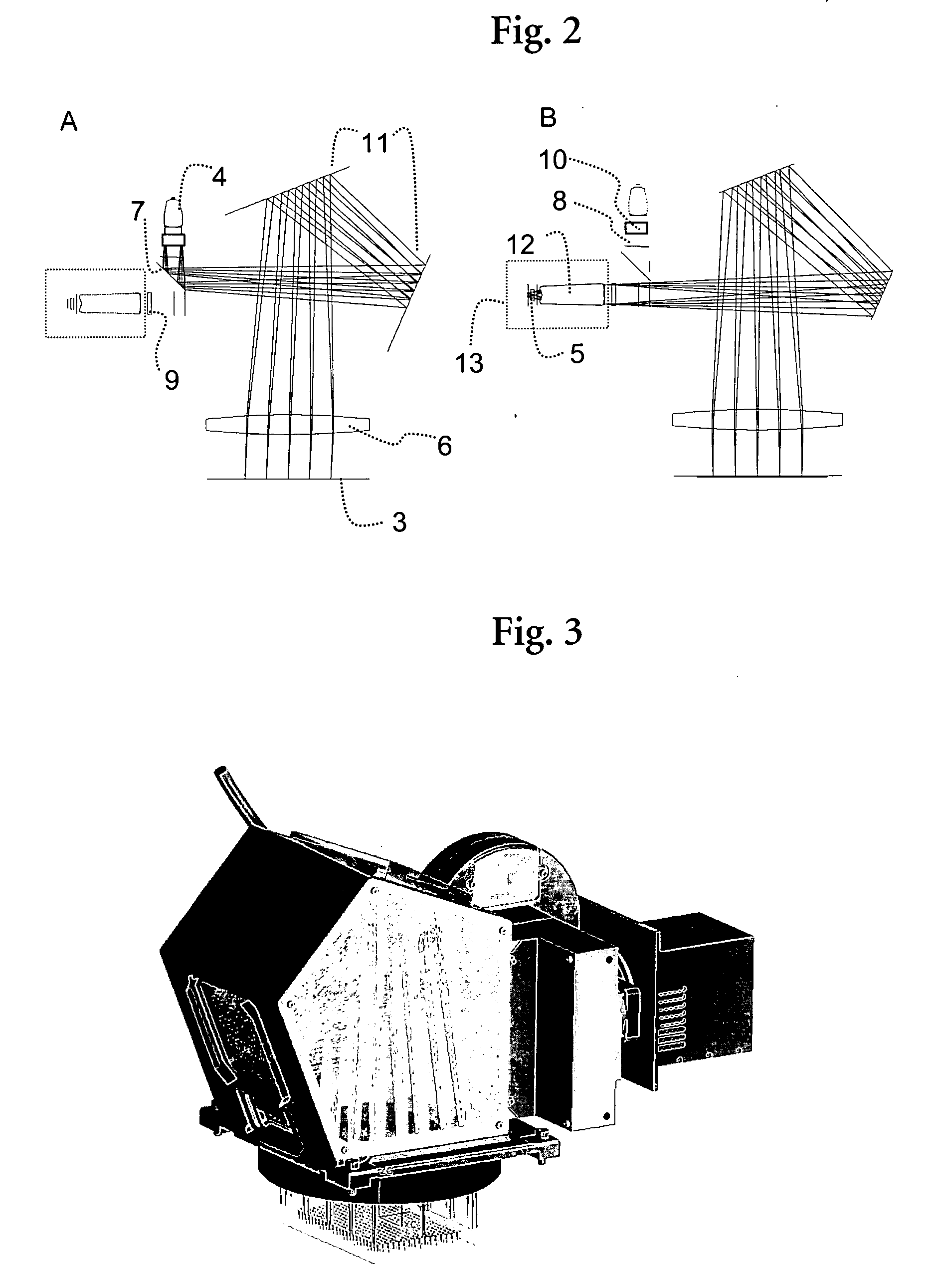
[0164] The following examples were performed with an optical instrument as explained in the detailed description and as visualized in FIG. 3. The telecentric excitation optic was adjusted to handle frequencies from 450 to 650 nm and the telecentric imaging optic to handle frequencies from 500 to 740 nm. The light source was a Xenon lamp and as transducer a cooled ⅔″ CCD chip with 1024×1344 pixels was used. The optical instrument was designed to image an area of 83 mm×117 mm so that microtiter plates (MTP) with 96 wells (distance 9 mm; diameter 5 mm) and 384 (distance 4.5 mm; diameter 3 mm) can be used. The appropriate wavelength for excitation and imaging for certain fluorescence dyes was adjusted by filter wheels.

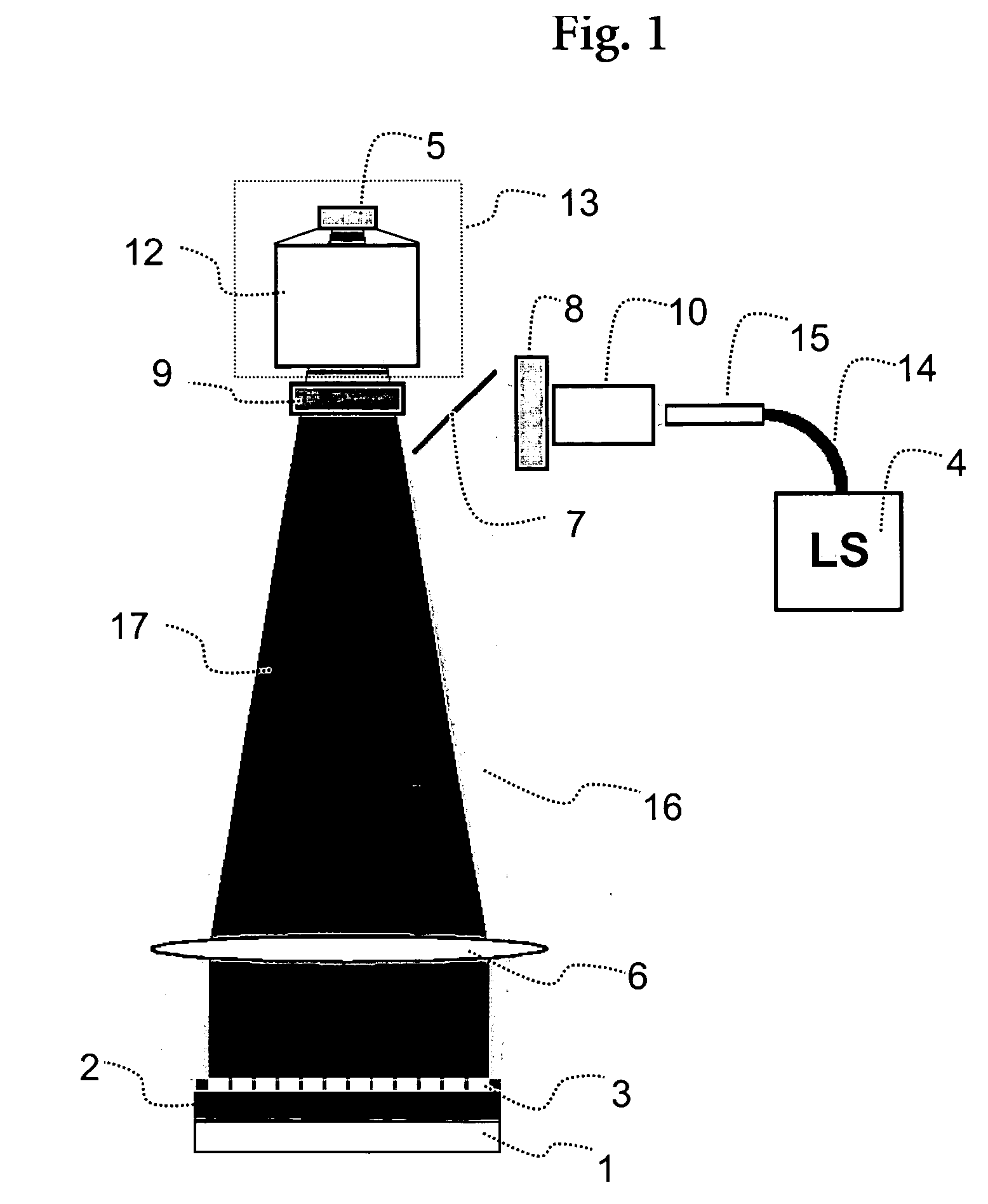
[0165] The telecentric excitation optic had a numerical aperture on the side of the light source of 0.35 and on the side of the MTP of 0.014. Due to geometric reasons, the light source was arranged perpendicular to the CCD chip and the excitation light beam had to be orie...

example 1

[0166] Sensitivity and Reproducibility

[0167] The sensitivity of an optical instrument as explained before was investigated with dilution series using fluorescein-sodium in water. Three different types of MTPs were tested, namely a black MTP (MTP 1), a transparent MTP (MTP 2) and a white MTP (MTP 3), and all providing about the same sensitivity. The measurements were performed at 58° C with an integration time of 1000 ms and were repeated 50 times for all points of the diagram of FIG. 5.

[0168] The 50 measurements mentioned above were used to test the reproducibility of the optical instrument, too and the progression of the intensity is illustrated in FIG. 6, exemplarily for a black MTP for two different optical instruments. Using the measurement values 20 to 50 for a fluorescein-sodium concentration in water of 85 nmol / l in 4 different wells using two MTP types and two different optical instruments, the following variations were obtained: 0.25% for MTP 1, 0.39% for MTP 2. For the w...

example 2

[0169] Crosstalk

[0170] An image of a transparent MTP with fluorescein-sodium in 5 wells is shown in FIG. 7. The image of the MTP shows two types of reflexions of the fluorescent wells. The first reflexion was detected within the distance to the neighboring wells, had the same diameter as and an intensity of about 0.5% from the well itself. The second reflexion had a diameter of around 2 to 3 times the diameter of the well itself and an intensity reduced by a factor of 2·104-3·104.

[0171] To summarize, the mean intensity at the neighboring wells is reduced by about a factor of 3·104 for the black MTP and by about a factor of 1·103 for the white MTP as well as for the transparent MTP.


PUM

PropertyMeasurementUnit
angle of incidenceaaaaaaaaaa

Abstract

The present invention relates to the field of DNA analysis. In particular, the present invention is directed to a device for the parallel imaging of fluorescence intensities at a plurality of sites as a measure for DNA hybridization. More particular, the present invention is directed to a device to image multiplex real time PCR or to read out DNA microarrays.

Description

RELATED APPLICATIONS [0001] This application claims priority to European patent application EP 05000863.0 filed Jan. 18, 2005. FIELD OF THE INVENTION [0002] The present invention relates to the field of DNA analysis. In particular, the present invention is directed to a device for the parallel imaging of fluorescence intensities at a plurality of sites. BACKGROUND OF THE INVENTION [0003] Various applications of fluorescence techniques to analyze biological samples are known to people skilled in the art. In case of electrophoretic techniques proteins or DNA are labeled with a fluorescence probe to visualize their electrophoretic bands in gels or columns. In addition, most biochip applications so far are based on a fluorescence read-out, whereas the specific binding of a fluorescence-labeled target molecule to a probe molecule immobilized on a solid support is monitored. Applications for DNA analysis in the liquid phase include fluorescence hybridization probes like the double-strande...

Claims


Application Information

Patent Timeline
Patent Type & Authority Applications(United States)
IPC IPC(8): C12M1/34C12M3/00
CPCG01J3/02G01J3/0208G01J3/021G01J3/4406G01N21/6428G01N21/6452G01N21/6456G01N35/028G01N2021/6478G01N2035/00158
Inventor GUTEKUNST, MARTINGUSE, FRANKHECKMANN, HANS-GEORGHESSLING, MARTINKOENIG, JOACHIM
Owner ROCHE DIAGNOSTICS OPERATIONS INC
Why Eureka
Try Eureka