Wiring protector

a wire protector and shielding technology, applied in the direction of coupling device details, coupling device connection, transportation and packaging, etc., can solve the problems of slack portion, affecting other components, and slack wires can become loose, so as to prevent the displacement of the tube and remove any residual looseness in the branch wire.

Inactive Publication Date: 2005-05-19
SUMITOMO WIRING SYST LTD
View PDF2 Cites 29 Cited by
  • Summary
  • Abstract
  • Description
  • Claims
  • Application Information

AI Technical Summary

Benefits of technology

[0008] Because the construction of the present invention adjusts the length of the branch wire by wrapping the branch wire around the radial perimeter of the adjusting member, damage to the branch wires, which would otherwise result from loosely hanging branch wires contacting components external to the wiring protector, is prevented. The construction of the present invention also prevents loosely hanging branch wires generating noise as a result of vehicle vibrations. Moreover, should the adjusting member be formed of an elastic material, pulling on the branch wire to connect the terminal end to a device connector has the effect of radially compressing the adjusting member. After the connection is made, the elastic material expands to its original condition, thereby removing the looseness from the branch wire.
[0010] The construction of the present invention, through which the adjusting member determines the direction that a branch wire exits the wiring protector, is thus able to control the direction of a branch wire and to ease the connection of branch wire terminal ends to devices.
[0011] The branch wire may be placed within an enclosing tube, and the branch wire, together with the enclosing tube, inserted into and secured within the branch wire guide channel. This construction of the present invention not only determines the direction that the branch wire exits the adjusting member, but also pinches the tube-enclosed branch wire between the sidewalls of the branch wire guide channel in the adjusting member, thus preventing displacement of the tube without the need to secure the tube with a tape wrapping.
[0013] This construction of the present invention allows the adjusting members to be attached to the wiring protector at any location where the direction and length of the branch wire are to be regulated.
[0015] The construction of the present invention employs gripping parts to compress the tube enclosing the branch wire, therefore preventing displacement of the tube without the use of a tape wrapping.
[0016] As previously noted, the wiring protector of the present invention adjusts the length of a branch wire by wrapping the branch wire around the perimeter of the adjusting member, and therefore is able to prevent damage caused by loosely hanging branch wires contacting objects external to the wiring protector and from generating noise induced by vehicle vibration. Moreover, if the adjusting member is made of an elastic material, pulling on the branch wire, at the time when the terminal connector of the branch wire is to be connected to a device, has the effect of radially compressing the adjusting member. After the connection is made, the elastic material expands and returns to its original shape, thereby removing any residual looseness in the branch wire.

Problems solved by technology

Branch wires w2 can become slack in the region external to protector 1 after connector 5 is attached to the terminal device, and the slack portion may interfere with other components.
This slackness can also result in the branch wires generating noise induced by vehicle vibration.

Method used


Image

  • Wiring protector
  • Wiring protector
  • Wiring protector

Examples


Embodiment Construction

[0033] The particulars shown herein are by way of example and for purposes of illustrative discussion of the embodiments of the present invention only and are presented in the cause of providing what is believed to be the most useful and readily understood description of the principles and conceptual aspects of the present invention. In this regard, no attempt is made to show structural details of the present invention in more detail than is necessary for the fundamental understanding of the present invention, the description is taken with the drawings making apparent to those skilled in the art how the forms of the present invention may be embodied in practice.

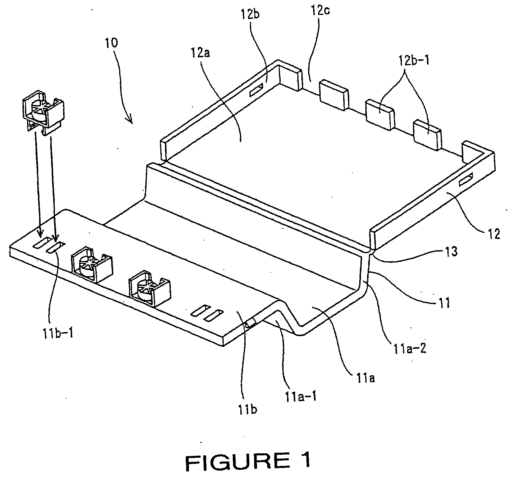
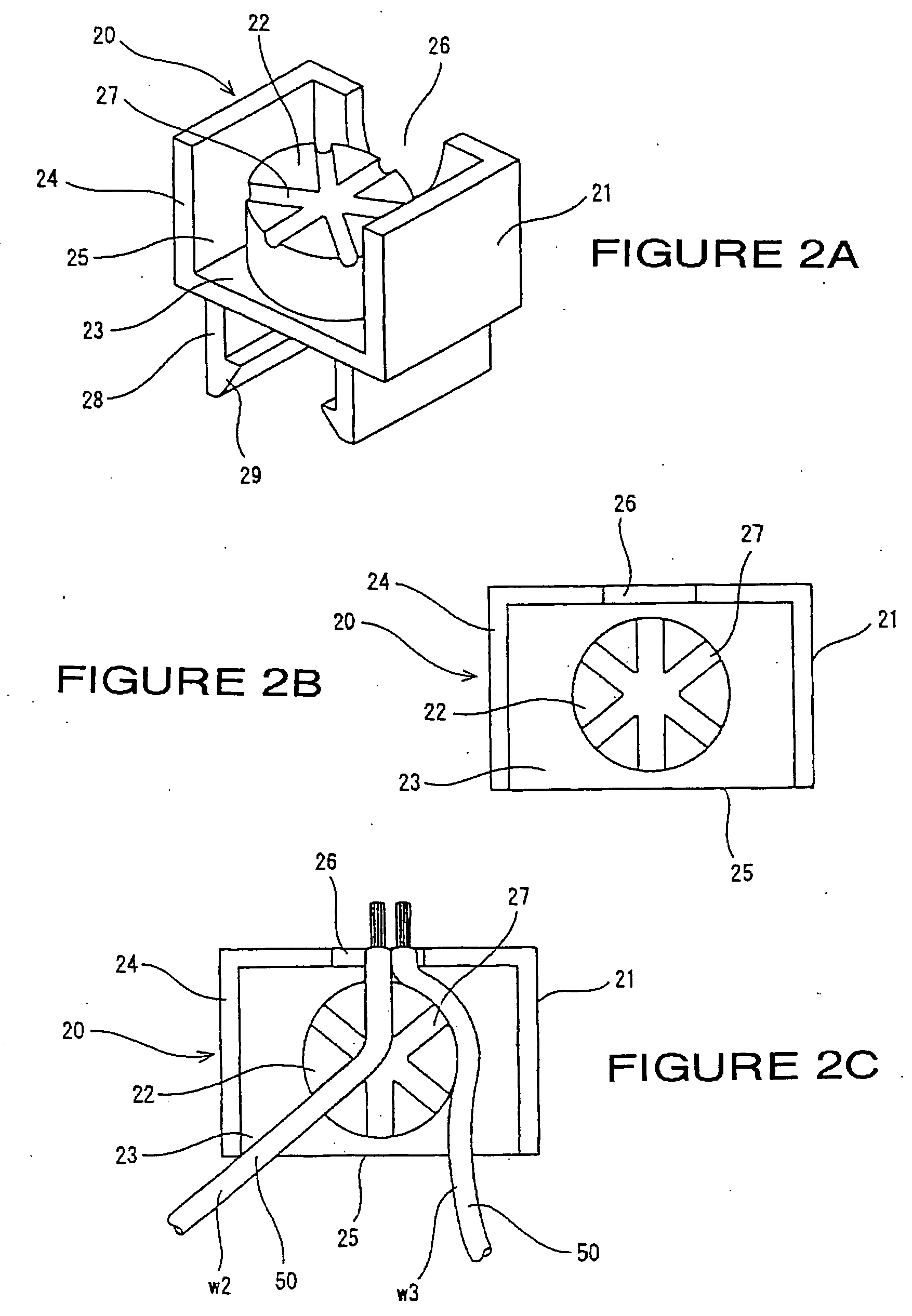
[0034] The following will describe the preferred embodiments with reference to the drawings. FIGS. 1, 2, 3, and 4 illustrate the first embodiment.

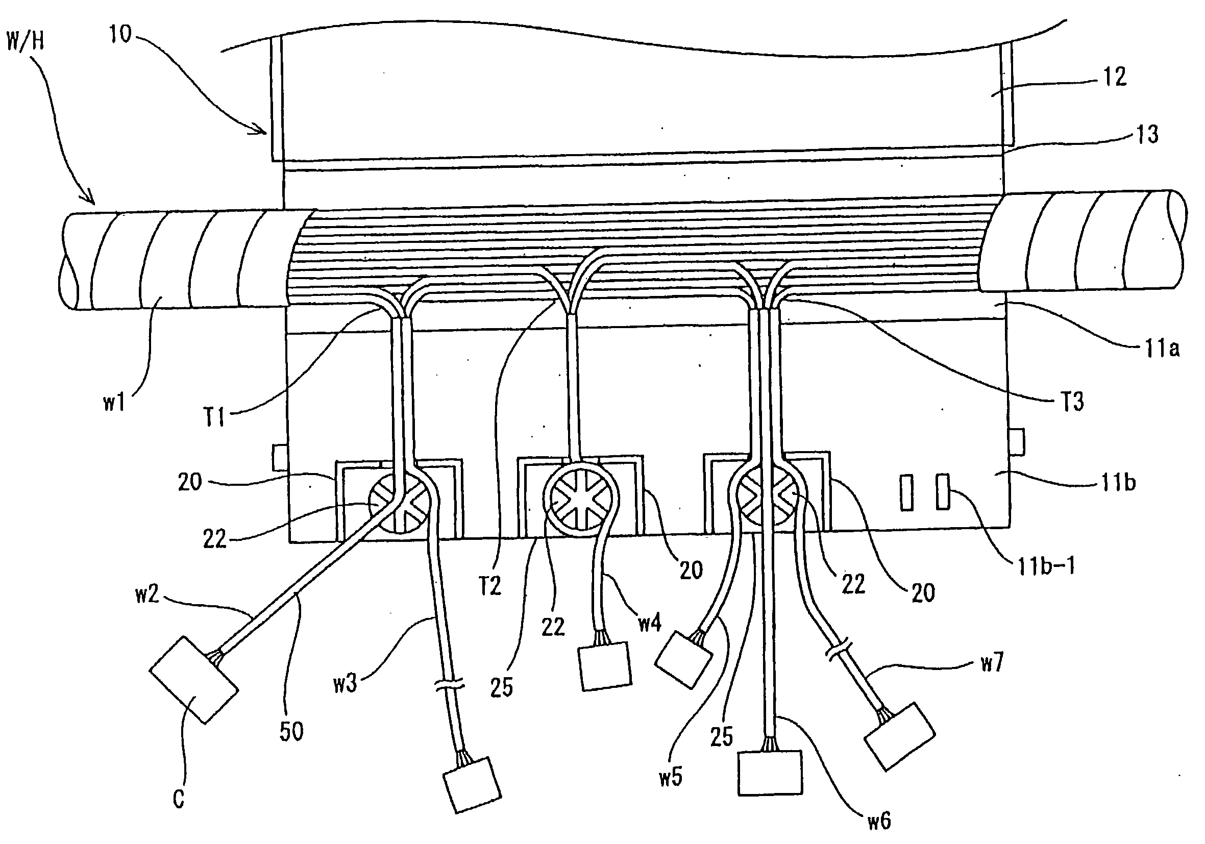
[0035]FIG. 1 illustrates wiring protector 10 as a component that may be installed in the engine compartment of an automobile at a location where wires branch off from wire harness...


PUM


Abstract

A wiring protector that controls the direction of exiting branch wires, secures a tube over the branch wires, and adjusts the length of the branch wires. Wire protector, which includes main body and a passageway formed therein through which trunk wires pass, is placed over a wire harness and attached to a vehicle body. Exit ports for branch wires are formed within the main body, and disk-shaped guide members or a clamp are attached to the internal region of the main body to control the exit direction of the branch wires and to determine the length of the branch wires.

Description

BACKGROUND OF THE INVENTION [0001] 1. Field of the Invention [0002] The present invention relates to a wiring protector, and more particularly to a wiring protector positioned over branch joints of a wiring harness that may be attached to a vehicle. The wiring protector establishes the direction that branch wires extend from the wiring harness, secures tubes attached to the branch wires, and adjusts the length of the branch wires. [0003] 2. Description of Background Information [0004] As shown in FIG. 8 and described by Japanese Kokai (Laid Open) Patent H9-117032, protector 1 is an example of a prior art wiring protector that fits over the branching wire locations of a wire harness attached to an automobile. Protector 1 is a one-piece structure that includes open-ended main body 2 which is placed around trunk wires w1 of wire harness WH at the location where branch wires separate therefrom, and lid 3 that exposes or covers the upper portion of main body 2 by pivoting on flexible hin...

Claims


Application Information

Patent Timeline
Patent Type & Authority Applications(United States)
IPC IPC(8): B60R16/02H01R9/24H01R13/58H02G3/04H02G3/08H02G3/38
CPCH01R13/5833H01R9/2416
Inventor HATORI, SHOUJI
Owner SUMITOMO WIRING SYST LTD
Why Eureka
Try Eureka