Teaching position correcting device

a technology for teaching positions and robots, applied in the direction of electric programme control, program control, instruments, etc., can solve the problems of difficult teaching correction work, position correction, and inability to use the motion program of the robot taught before the line is moved, so as to improve teaching accuracy and teaching accuracy. , the effect of reducing load

Inactive Publication Date: 2005-05-19
FANUC LTD
View PDF7 Cites 104 Cited by
  • Summary
  • Abstract
  • Description
  • Claims
  • Application Information

AI Technical Summary

Benefits of technology

[0019] The present invention has been made to solve the above problems, and has an object of providing a device that can easily correct in high precision teaching positions after a shifting and can reduce load on an operator who corrects the teaching associated with the shifting.

Problems solved by technology

Therefore, a motion program for the robot that is taught before the line is moved cannot be used as it is, and the teaching position needs to be corrected.
This teaching correction work is very troublesome.
Particularly, when the line that uses many robots in a spot welding of an automobile is to be moved, the number of steps of this teaching correction work is enormous.
According to the above methods using mechanical means, positional precision after the re-setting is usually about a few centimeters, and it is practically difficult to secure higher precision.
Therefore, teaching correction work to solve the remaining error is unavoidable.
It is difficult to match a three-dimensional orientation change due to falling or inclining, for example.
However, in actual practice, the finally obtained program cannot easily achieve high-precision work because of presence of both or one of a setting error of the TCP of the robot and a positioning error of the touchup to the reference points.
Particularly, because positioning is carried out based on visual measurement, even a skilled operator cannot achieve high-precision work.
It takes time to correctly carry out TCP setting and touchup.
As described above, despite users' request for carrying out an accurate correction of teaching positions associated with the shifting of the robot and the workpiece in a short time, there is no practical method to achieve this.

Method used


Image

  • Teaching position correcting device
  • Teaching position correcting device
  • Teaching position correcting device

Examples


Embodiment Construction

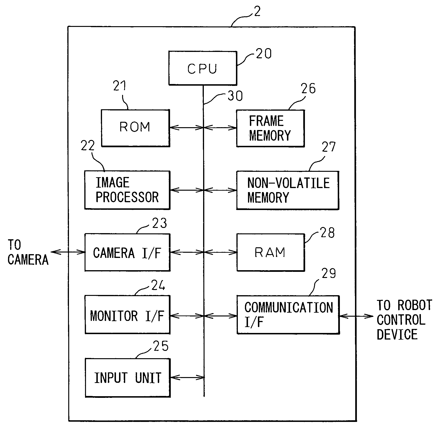
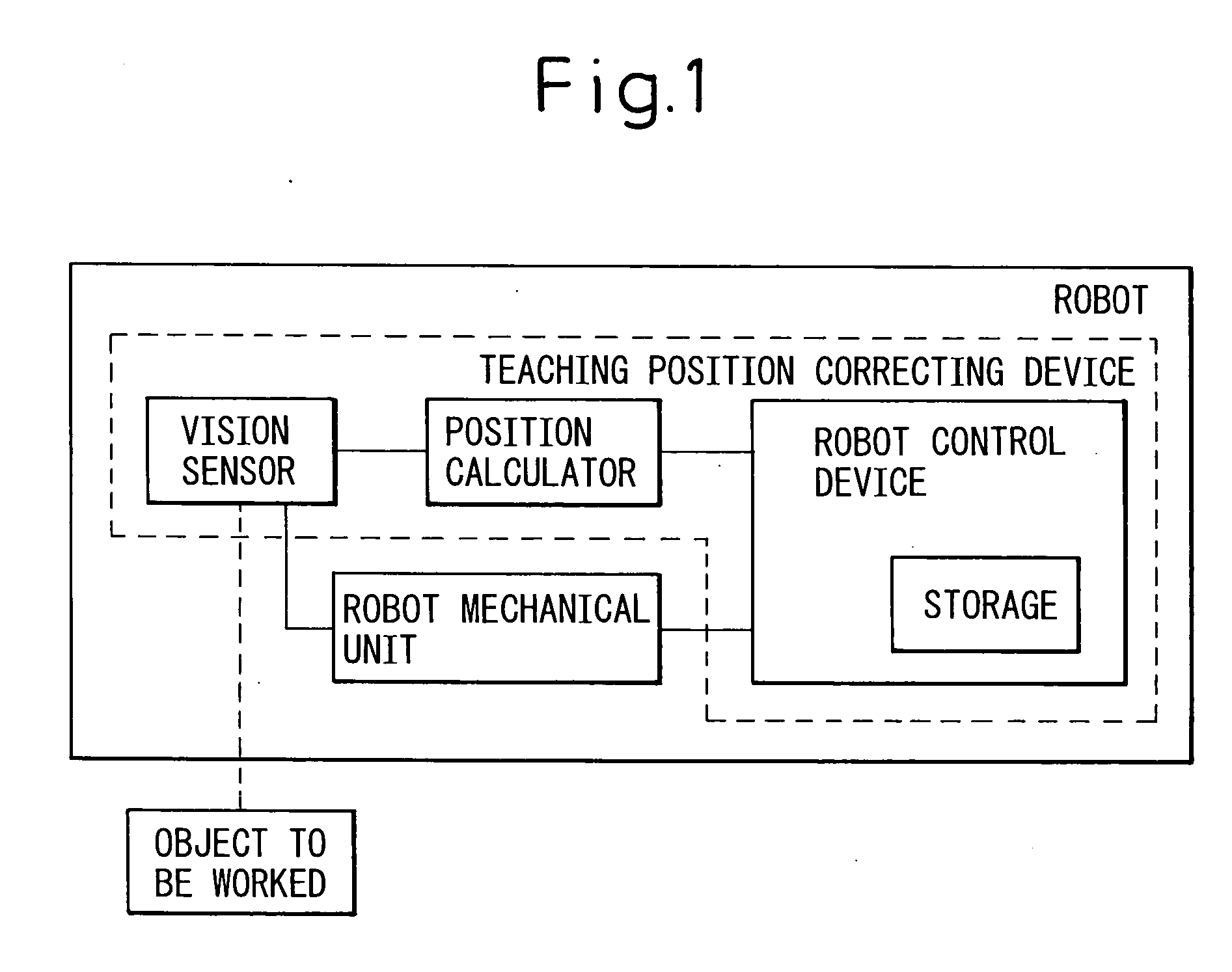
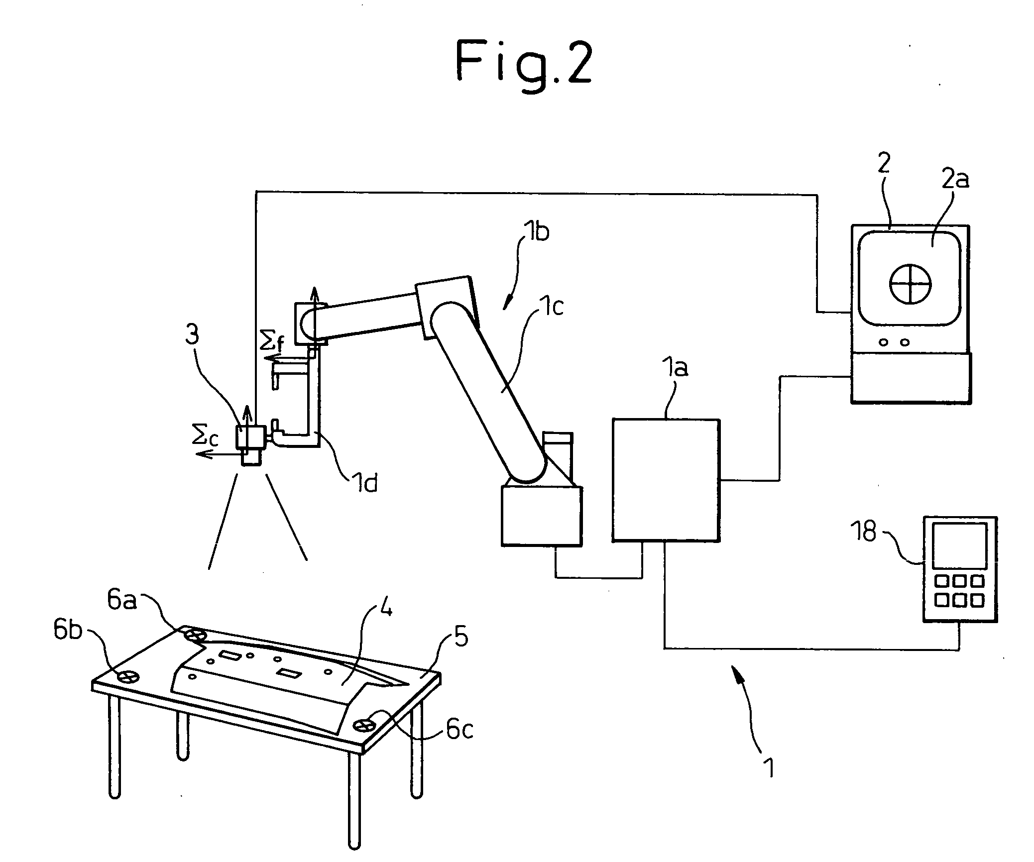
[0041] A teaching position correcting device according to embodiments of the present invention is explained below with reference to the drawings. As shown in FIG. 1, the teaching position correcting device according to the present invention is designed to correct a teaching position of a motion program for a robot when at least one of the robot having a robot mechanical unit and an object to be worked by the robot is moved. The teaching position correcting device has: a storage that stores the teaching position of the motion program; a vision sensor that is configured to measure a three-dimensional position of each of at least three sites not aligned in a straight line on the object to be worked by the robot; a position calculator that obtains a three-dimensional position of each of the at least three sites before and after a change respectively of a position of the robot mechanical unit relative to the object to be worked, based on measured data obtained by the vision sensor; and a...


PUM


Abstract

A teaching position correcting device which can easily correct, with high precision, teaching positions after shifting at least one of a robot and an object worked by the robot. Calibration is carried out using a vision sensor (i.e., CCD camera) that is mounted on a work tool. The vision sensor measures three-dimensional positions of at least three reference marks not aligned in a straight line on the object. The vision sensor is optionally detached from the work tool, and at least one of the robot and the object is shifted. After the shifting, calibration (this can be omitted when the vision sensor is not detached) and measuring of three-dimensional positions of the reference marks are carried out gain. A change in a relative positional relationship between the robot and the object is obtained using the result of measuring three-dimensional positions of the reference marks before and after the shifting respectively. To compensate for this change, the teaching position data that is valid before the shifting is corrected. The robot can have a measuring robot mechanical unit having a vision sensor, and a separate working robot mechanical unit that works the object. In this case, positions of the working robot mechanical unit before and after the shifting, respectively, are also measured.

Description

BACKGROUND OF THE INVENTION [0001] 1. Field of the Invention [0002] The present invention relates to a teaching position correcting device for a robot. Particularly, the invention relates to a teaching position correcting device that is used to correct a teaching position of a motion program for a robot when at least one of the robot and an object to be worked is moved. [0003] 2. Description of the Related Art [0004] When a production line using a robot is moved, one of or both the robot and an object to be worked, i.e., a workpiece, are often moved as in the following cases. [0005] A line in operation is shifted to a separate position. For example, the whole production line is moved to a separate plant, possibly overseas. [0006] Once a system is started at a separate place, the system is shifted to and set in the production site. For example, once a new line is started in a provisional plant, the operation in the line is confirmed, and then the line is moved to an actual production...

Claims


Application Information

Patent Timeline
Patent Type & Authority Applications(United States)
IPC IPC(8): B25J9/10B25J9/16B25J13/08G05B19/401G05B19/404G05B19/408G05B19/42
CPCB25J9/1692G05B19/4083G05B2219/39057G05B2219/37555G05B2219/39024G05B2219/36504
Inventor BAN, KAZUNORITAKIZAWA, KATSUTOSHI
Owner FANUC LTD
Why Eureka
Try Eureka