
Airbag apparatus

a technology of airbags and g sensors, which is applied in the direction of pedestrian/occupant safety arrangements, instruments, and tractors, etc., can solve the problems of airbag apparatus, ecu may not be able to process the g level values from the g sensor disposed, and the ecu is imposed on loads, so as to reduce the time required to determine the occurrence of collisions

Inactive Publication Date: 2005-05-19
FUJITSU GENERAL LTD
View PDF7 Cites 35 Cited by
  • Summary
  • Abstract
  • Description
  • Claims
  • Application Information

AI Technical Summary

Benefits of technology

[0004] The “threshold value determination by the ECU” referred to here means the following processing. The ECU integrates outputs (acceleration values) from the G sensors for a predetermined period, and when the integral value exceeds a predetermined threshold value, the ECU determines that collision by another vehicle has occurred. That is, the threshold value serves as a criterion for inflation of a side airbag. By means of employing acceleration values in such a manner, error detection is prevented in the event that a momentary output is generated, whereby judgment accuracy on collision is increased.
[0007] The invention has been conceived in light of the hitherto-described problems, and provides an airbag apparatus, which can shorten the time required to determine occurrence of a collision when a lateral collision with another vehicle is detected.
[0008] To solve the problem cited above and to achieve the object, according to one embodiment of the invention, an airbag apparatus includes a controller, a prediction unit, and a sampling-period control unit. The controller conducts sampling of acceleration values output from a plurality of acceleration sensors disposed on a vehicle and controls inflation of an airbag based on the sampled acceleration values. The prediction unit predicts a collision direction in which collision with another vehicle would occur. When the prediction unit predicts the collision direction, the sampling-period control unit shortens a sampling period for the acceleration sensor disposed in the predicted collision direction in comparison with sampling period for the other acceleration sensors. After the sampling-period control unit shortens the sampling period, the controller determines whether or not to inflate the airbag, based on the sampled acceleration values output from the acceleration sensor disposed in the predicted collision direction.
[0009] With this configuration, since delay due to communication processing and arithmetic processing is prevented, delay in inflation of a side airbag can be prevented. In addition time required to determine occurrence of collision can be shortened. As a result, an advantage of the ability to reliably protect occupants is achieved.
[0011] With this configuration, the time required to determine occurrence of a collision can be shortened.

Problems solved by technology

However, the airbag apparatus described above has the following problems.
However, since it is hard for the ECU to process (integrate) the G level values detected by the respective G sensors simultaneously, the ECU integrates the G level values from the respective G sensors in a predetermined sequence.
As the result, there is a problem that, when an actual collision occurs, the ECU may not be able to process the G level values from the G sensor disposed at a collision point.
On the other hand, if the ECU processes the G level values from the plural G sensors simultaneously, there is a problem that loads are imposed on the ECU.

Method used


Image

  • Airbag apparatus
  • Airbag apparatus
  • Airbag apparatus

Examples


first embodiment

[0039] As shown in FIGS. 1 and 2, the airbag apparatus includes a plurality of G sensors 31 to 36 (side-impact sensors) for detecting a lateral collision, at predetermined positions (on the right and left sides) of a vehicle 10. An airbag controller 2 (FIG. 3) predicts a collision direction (collision position) of collision with another vehicle on the basis an integral value (G integral value) of acceleration values output from the respective G sensors 31 to 36. The airbag controller 2 performs processing of shortening the sampling period of G sensors disposed in the predicted collision direction (predicted collision portion) or performs processing of giving a preference in the sampling order to the sampling of the G sensors disposed in the predicted collision direction (predicted collision portion). Consequently, by virtue of the above, in addition to detecting collision direction of a collision with another vehicle prior to the collision, the airbag apparatus according to the embo...

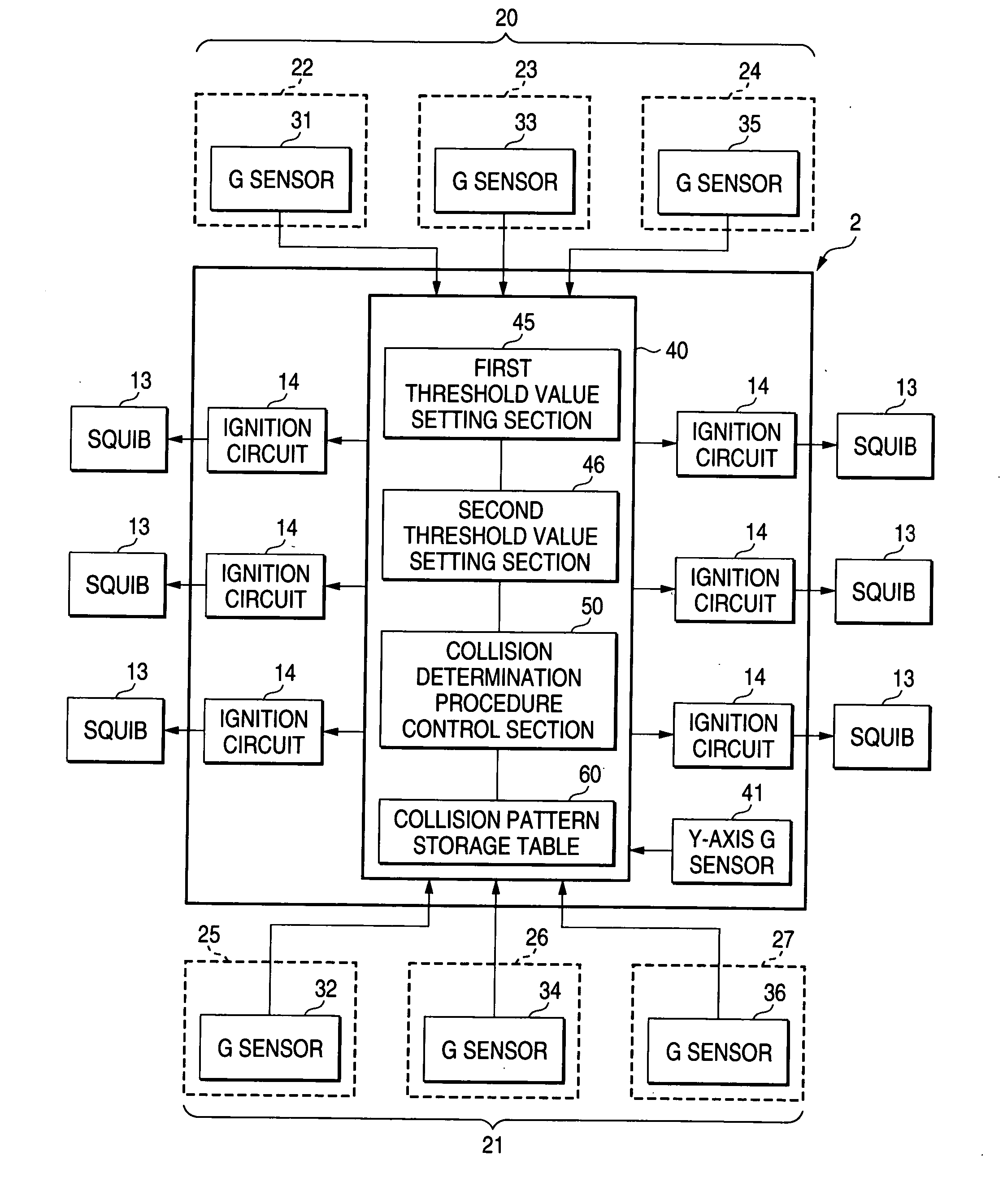
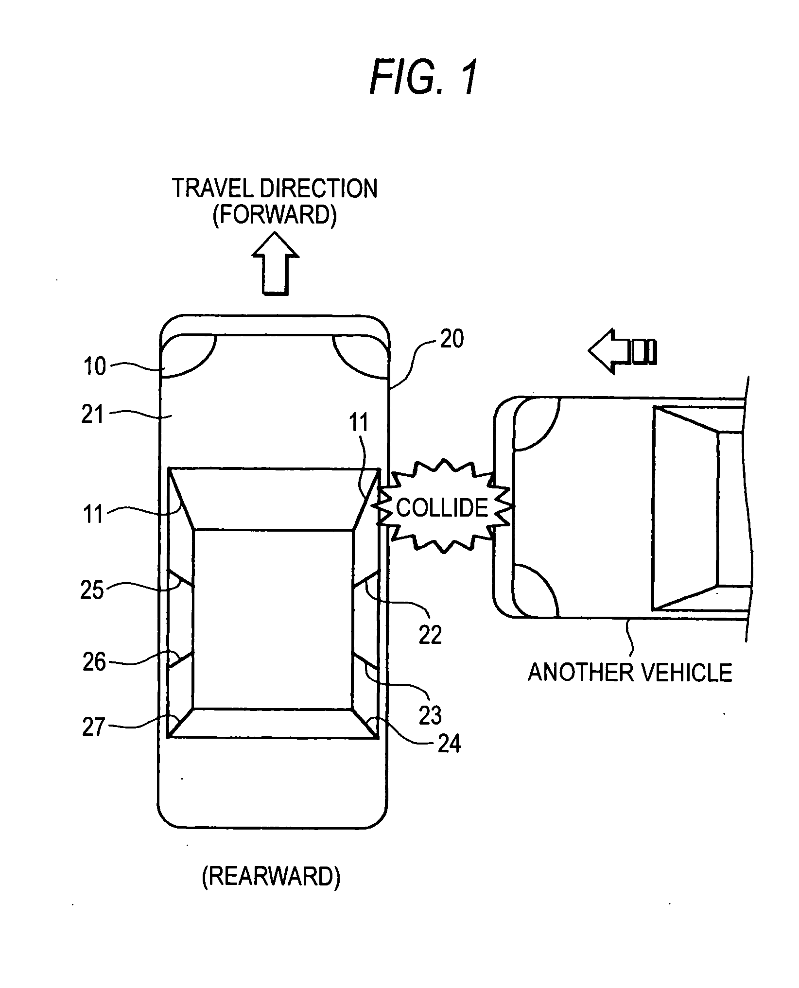
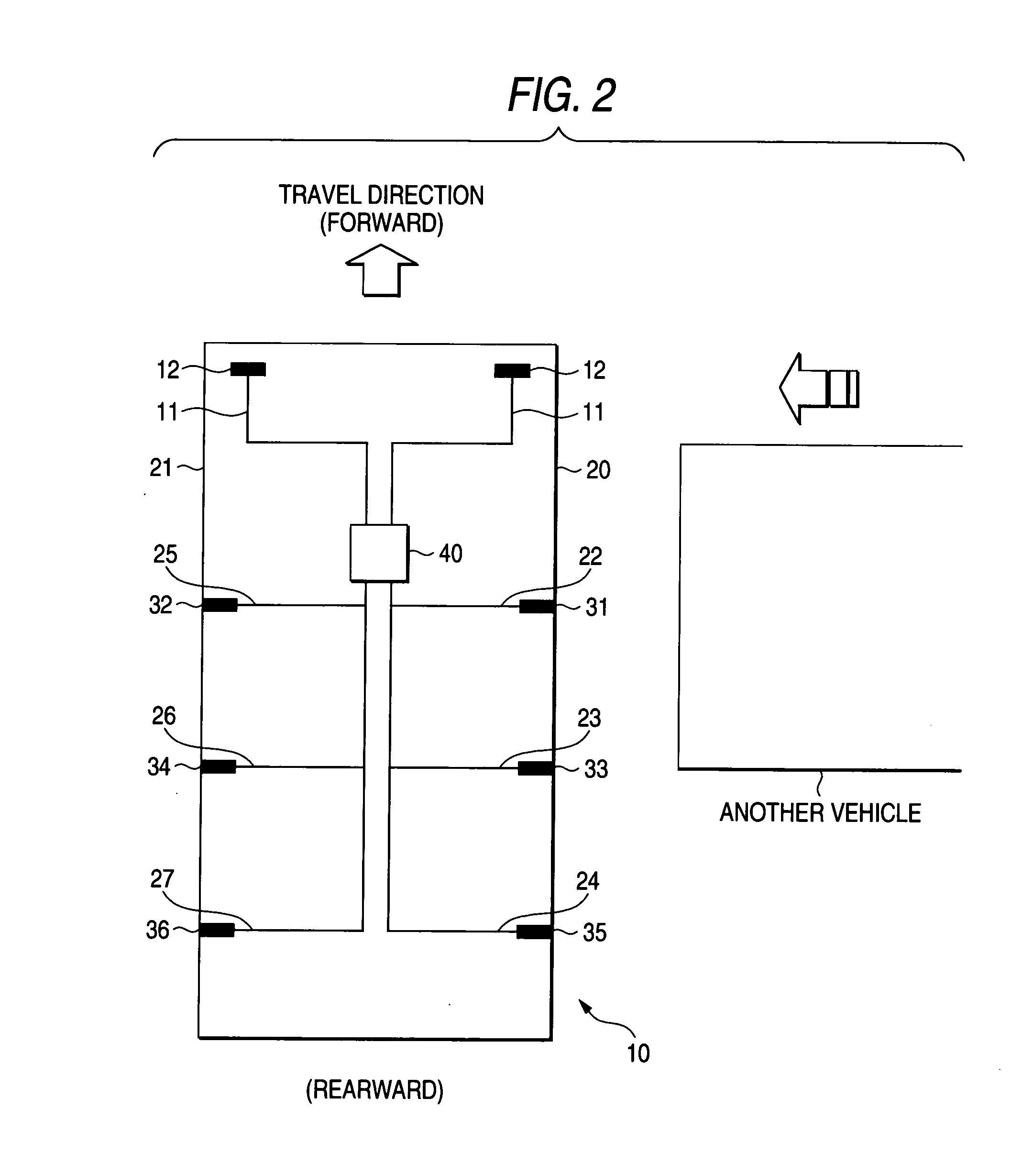
second embodiment

[0060] Next, a second embodiment of the invention will be described in detail with reference to FIG. 7. In the first embodiment, a collision direction (on the right side surface 20 or on the left side surface 21) of a collision with another vehicle is determined (predicted) on the basis of integral values of acceleration values output from the plurality of G sensors, and the sampling period for the G sensors located in the thus-determined (predicted) collision side is shortened. However, in the second embodiment, the collision-position prediction section 53 (FIG. 4) specifies a collision portion of collision with another vehicle; and the sampling period of only the G sensor located at the collision position specified by the collision-position prediction section 53 is shortened.

[0061] More specifically, as shown in the flowchart shown in FIG. 7, the ECU 40 integrates acceleration values output from the plurality of G sensors 31 to 36 subsequently (step S210). Then, the integral-valu...

third embodiment

[0064] Next, a third embodiment of the invention will be described in detail with reference to the flowchart shown in FIG. 8. In the respective embodiments shown in FIGS. 8 to 25 below, detailed descriptions of the same processes as those in the hitherto-described flowchart shown in FIG. 5 will be omitted.

[0065] In the hitherto-described first and second embodiments, a collision direction (on the right side surface 20 or on the left side surface 21) or a collision position of a collision with another vehicle is determined (predicted) on the basis of G level values (G integral values) detected by the plurality of G sensors, and the sampling period of the plurality of G sensors located in the thus-determined predicted-collision side or only the G sensor located at the collision-predicted portion is shortened (0.5 ms→0.25 ms). However, in the third embodiment, the sampling-sequence control section 56 causes the plurality of G sensors located in the collision direction, which has been ...


PUM


Abstract

An airbag apparatus includes a controller, a prediction unit, and a sampling-period control unit. The controller conducts sampling of acceleration values output from a plurality of acceleration sensors disposed on a vehicle and controls inflation of an airbag based on the sampled acceleration values. The prediction unit predicts a collision direction in which collision with another vehicle would occur. When the prediction unit predicts the collision direction, the sampling-period control unit shortens a sampling period for the acceleration sensor disposed in the predicted collision direction in comparison with sampling period for the other acceleration sensors. After the sampling-period control unit shortens the sampling period, the controller determines whether or not to inflate the airbag, based on the sampled acceleration values output from the acceleration sensor disposed in the predicted collision direction.

Description

1. FIELD OF THE INVENTION [0001] The present invention relates to an airbag apparatus, which protects occupants by means of inflating an airbag upon detection of a collision, and more particularly to an airbag apparatus, which enables early determination of occurrence of collision, as well as shortening the time required to determine occurrence of collision, by means of predicting a collision direction (collision portion). 2. DESCRIPTION OF THE RELATED ART [0002] As an airbag apparatus for protecting occupants, there has hitherto been known an airbag apparatus, which protects in-vehicle occupants by means of instantly inflating an airbag accommodated in the center of a driver's seat (a steering wheel) in the event of detection of a collision (head-on collision) with another vehicle. In addition, there has recently been known an airbag apparatus, which protects occupants, in the event of a collision with another vehicle on the side of a vehicle, by means of inflating a side airbag di...

Claims


Application Information

Patent Timeline
IPC IPC(8): B60R21/01B60R21/0132B60R21/0134
CPCB60R21/0132B60R2021/01325B60R21/0134B60R21/0133B60R2021/01184
Inventor KURODA, SHUUSAKUTANAKA, SEIGOFUMIIWA, MASANOBUSUGIE, AKIRA
Owner FUJITSU GENERAL LTD
Learn More