Axle assembly for mounting a wheel to a vehicle

Active Publication Date: 2005-05-26
SRAM CORPORATION
View PDF19 Cites 60 Cited by
  • Summary
  • Abstract
  • Description
  • Claims
  • Application Information

AI Technical Summary

Benefits of technology

[0005] One object of the present invention is to provide an axle assembly that provides a very rigid

Problems solved by technology

During a typical ride, a rider will encounter irregularities in the terrain that are transmitted through the wheel and fork to the handlebars.
Terrain irregularities create hig

Method used


Image

  • Axle assembly for mounting a wheel to a vehicle
  • Axle assembly for mounting a wheel to a vehicle
  • Axle assembly for mounting a wheel to a vehicle

Examples


Embodiment Construction

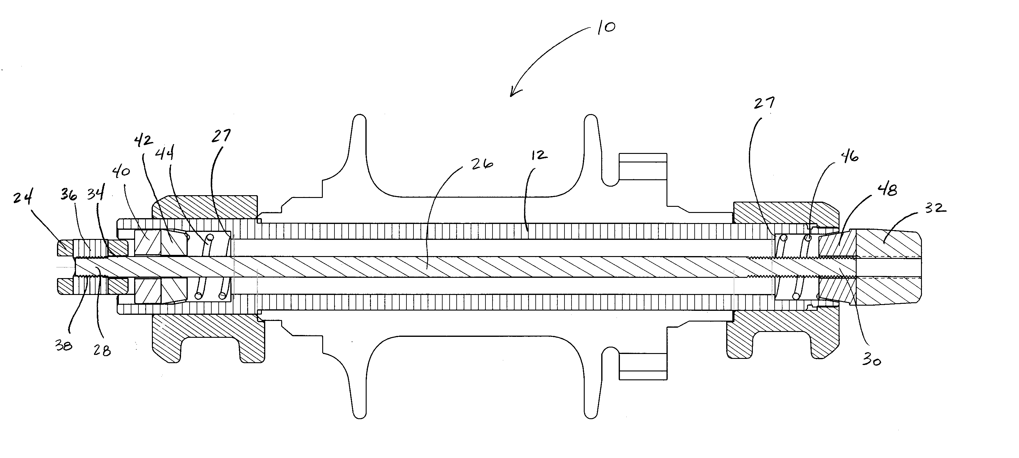
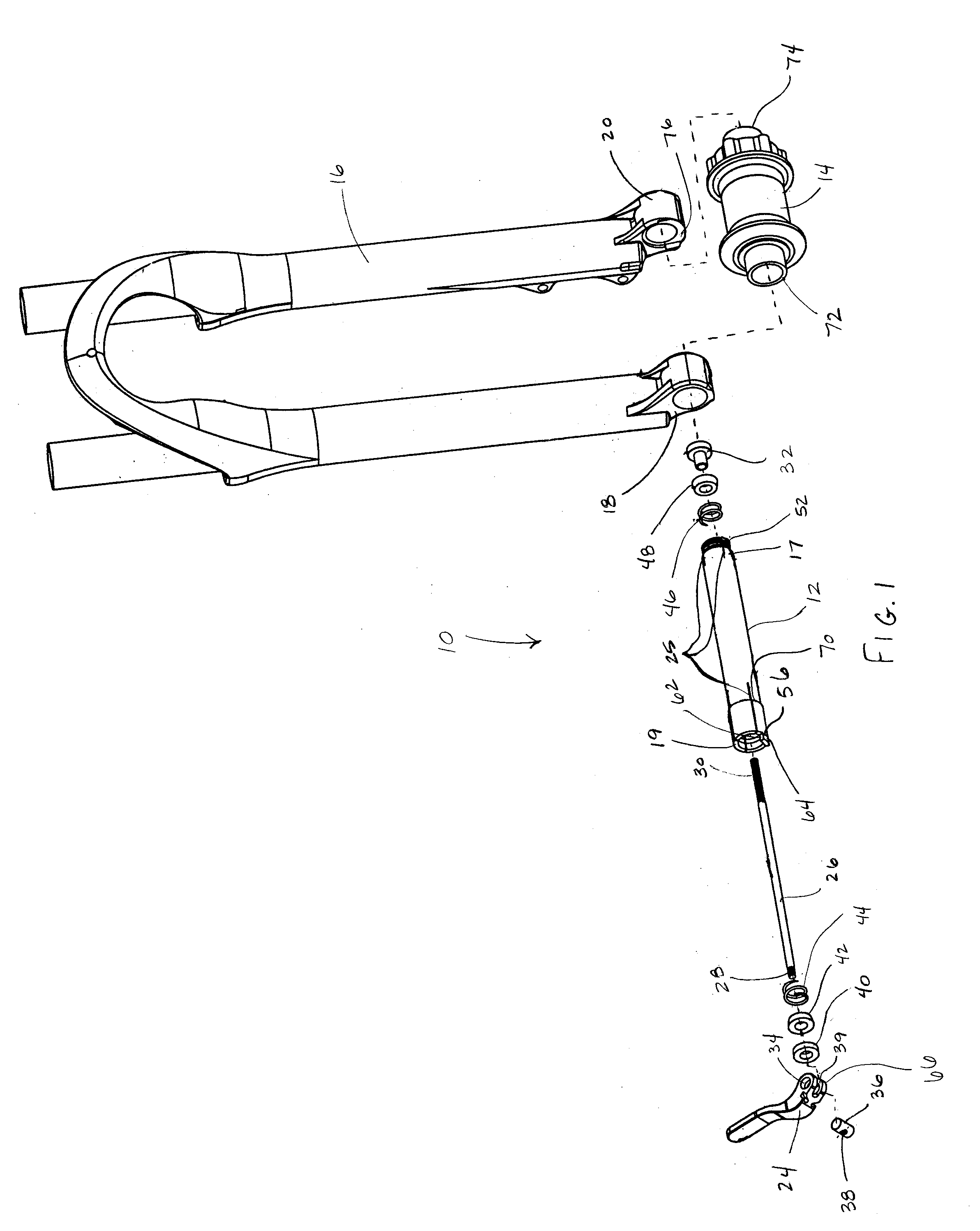
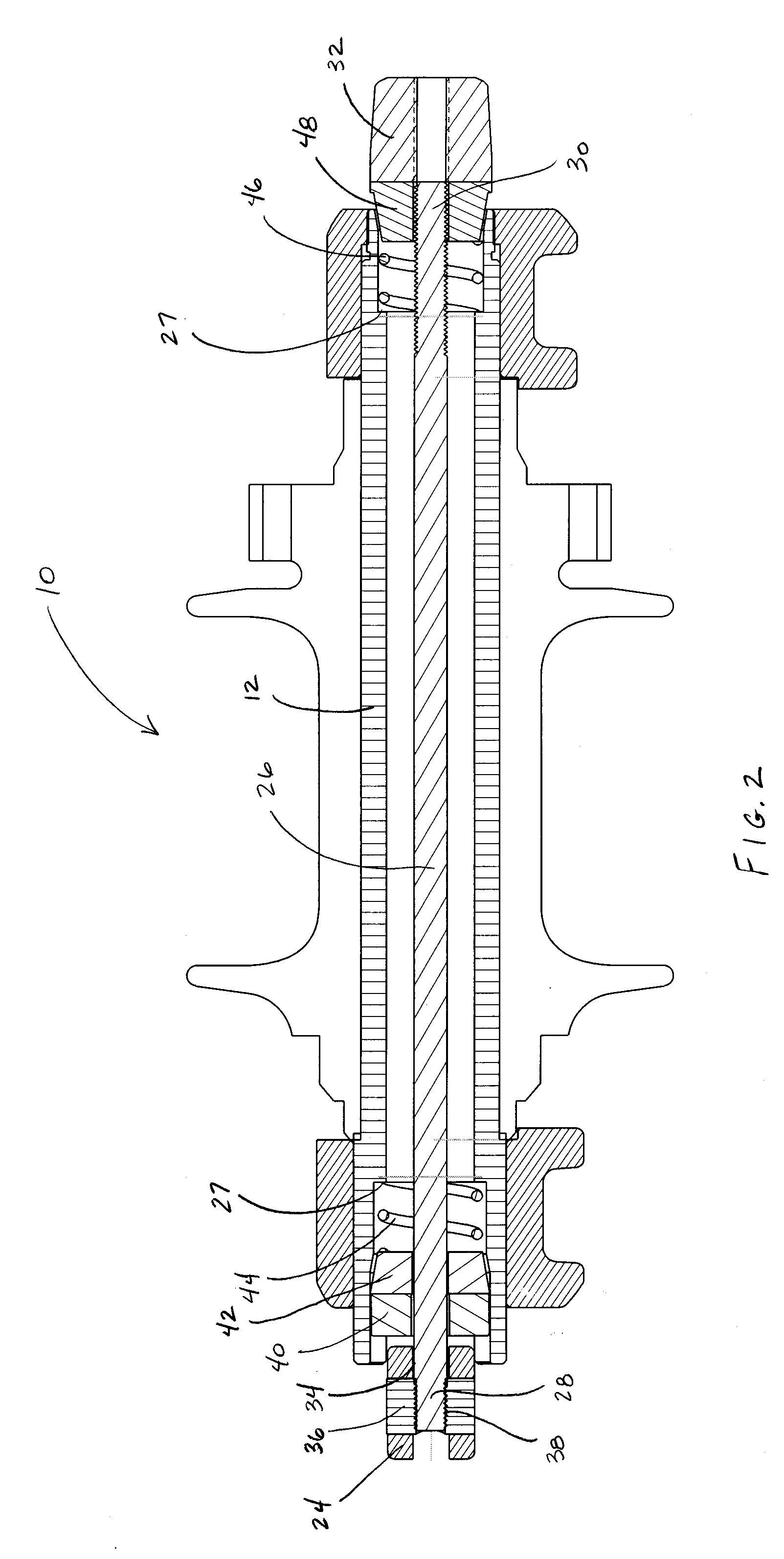
[0024] Looking to FIGS. 1-6, a first embodiment of an axle assembly according to the present invention is designated generally by the reference number 10. The axle assembly 10 connects a front wheel hub 14 of a bicycle to a front suspension fork 16. Alternatively, the axle assembly 10 may be used to connect a rear wheel to a bicycle frame or a motorcycle wheel to a motorcycle frame. The axle assembly 10 extends coaxially through the wheel hub 14, mounting to dropouts 18, 20 of the suspension fork 16. The axle assembly generally includes a tubular body 12 having first and second ends 17, 19. The wheel hub 14 mounts rotatably on the tubular body 12, and the first and second ends 17, 19 of the tubular body mount to the dropouts 20, 18 of the fork 16.

[0025] In the embodiment of FIGS. 1-6, the first end 17 of the tubular body 12 is threaded into the dropout 20 of the fork 16, while the second end 19 of the tubular body 12 is associated with a clamp lever 24 configured to pivotably clamp...


PUM


Abstract

An axle assembly connecting a wheel assembly to a vehicle frame. The axle assembly includes a tubular body having first and seconds connectable to the vehicle frame and open-ended slots disposed proximate at least one of the first and second ends of the tubular body. An expansion element is engageable with the tubular body to radially deform the tubular body at a mounting point to the vehicle frame. This configuration provides a rigid connection between the axle assembly and the vehicle frame in both the linear and radial directions.

Description

BACKGROUND OF INVENTION [0001] The present invention relates to axle assemblies for mounting wheel hubs to handlebar-steered vehicles, and more particularly to an axle assembly that securely mounts a wheel hub to a suspension fork to provide a torsionally stiffer front suspension assembly. [0002] Typically, in handlebar-steered vehicles like bicycles and motorcycles, an axle assembly is used to mount a wheel hub to a fork. The fork includes parallel legs that extend upward from each side of the axle and connect at the top of the wheel at a central steering tube that forms part of the bicycle or motorcycle frame. The bottom end of the fork legs are typically u-shaped or annular dropouts shaped for receiving the axle assembly. The axle may be mounted to the dropouts with a quick-release mounting device. Such devices facilitate removal of the wheel for repairs, transport, storage, etc. [0003] During a typical ride, a rider will encounter irregularities in the terrain that are transmitt...

Claims


Application Information

Patent Timeline
IPC IPC(8): B62K25/02
CPCY02T10/86B62K25/02
Inventor ROSE, RUSSELLHERRINGTON, EDWARDREID, JOHNOSBORNE, JAMES
Owner SRAM CORPORATION
Why Eureka
Try Eureka