
Signal receiver devices and methods

a signal receiver and receiver technology, applied in the field of signal receiver devices and methods, can solve problems such as poor reception, interference rejection methods of prior art, and common consideration of multi-user detection techniques only, and achieve the effect of more robust interference rejection

Inactive Publication Date: 2005-05-26
HIGHBRIDGE PRINCIPAL STRATEGIES LLC AS COLLATERAL AGENT
View PDF10 Cites 33 Cited by
  • Summary
  • Abstract
  • Description
  • Claims
  • Application Information

AI Technical Summary

Benefits of technology

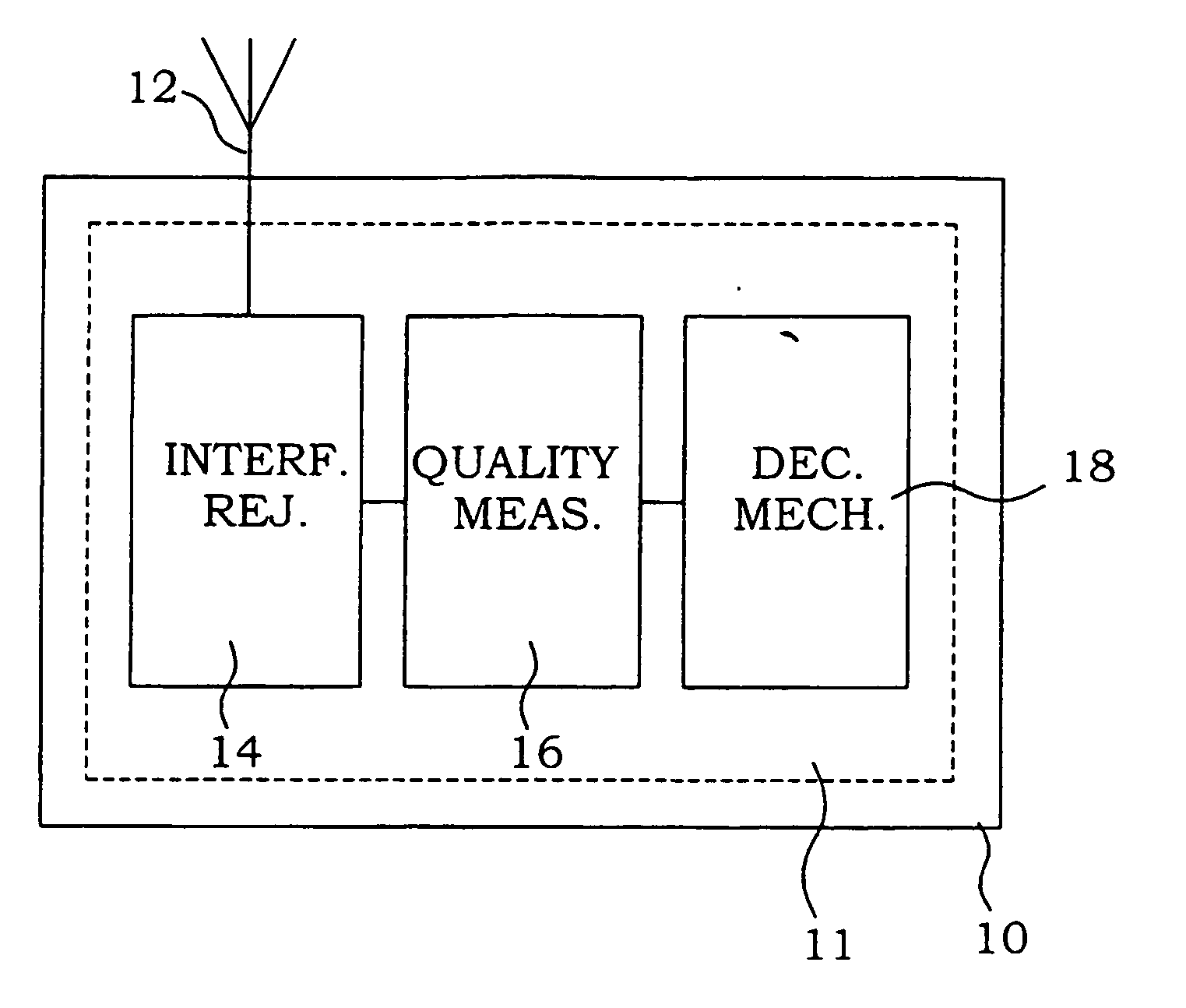
[0012] A general object of the present invention is to provide methods, devices and systems for more robust interference rejection. A further object of the present invention is to provide methods, devices and systems for detecting the character of the impairment in the received signal.

Problems solved by technology

This causes the receivers to work poorly when the level of interference is high.
However, multi-user detection techniques are commonly only considered for base-stations as they are complex in both radio and baseband signal processing.
However, the interference rejection methods of prior art suffer from some problems.
One major problem in this context is that in scenarios where these model assumptions are not true, the performance of the receivers might instead deteriorate.
One example is that interference rejection methods might work poorly in noise limited environments, i.e. when no interference is present.
For systems that utilize more than one modulation scheme, e.g. the evolution of GSM / GPRS, which is called EDGE (Enhanced Data rates for Global Evolution), there is, however, a problem.
When the modulation scheme of the carrier and interferer do not fulfill the assumptions under which the interference rejection method was designed, the performance of the interference rejection receiver might in certain cases deteriorate, and even be worse than a conventional receiver without interference rejection capabilities.
Hence, with 8PSK-modulated interference it is not possible to estimate the I / Q correlation accurately during the training sequence, and, consequently, trying to remove it during the rest of the burst degrades the overall performance.

Method used


Image

  • Signal receiver devices and methods
  • Signal receiver devices and methods
  • Signal receiver devices and methods

Examples


first embodiment

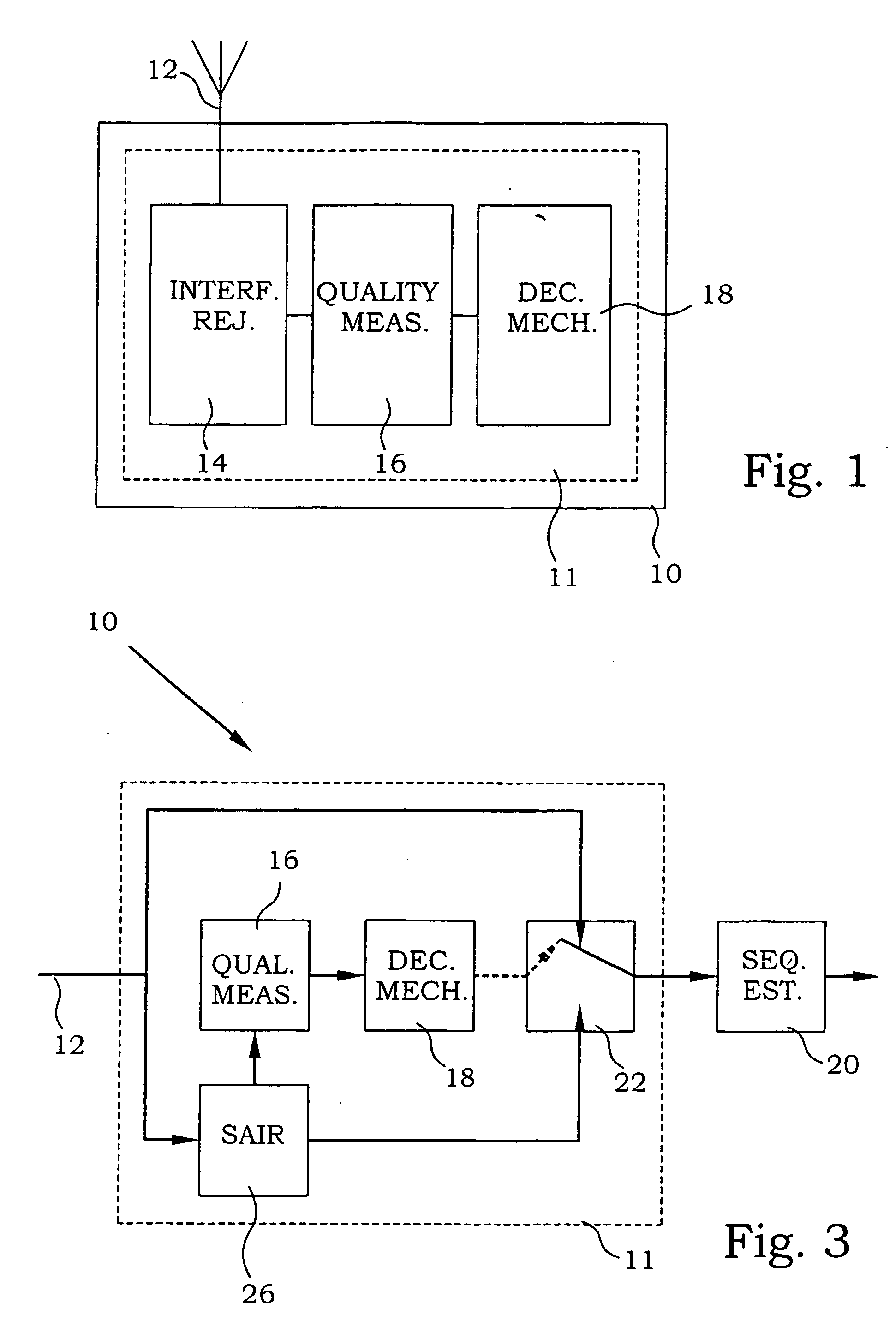
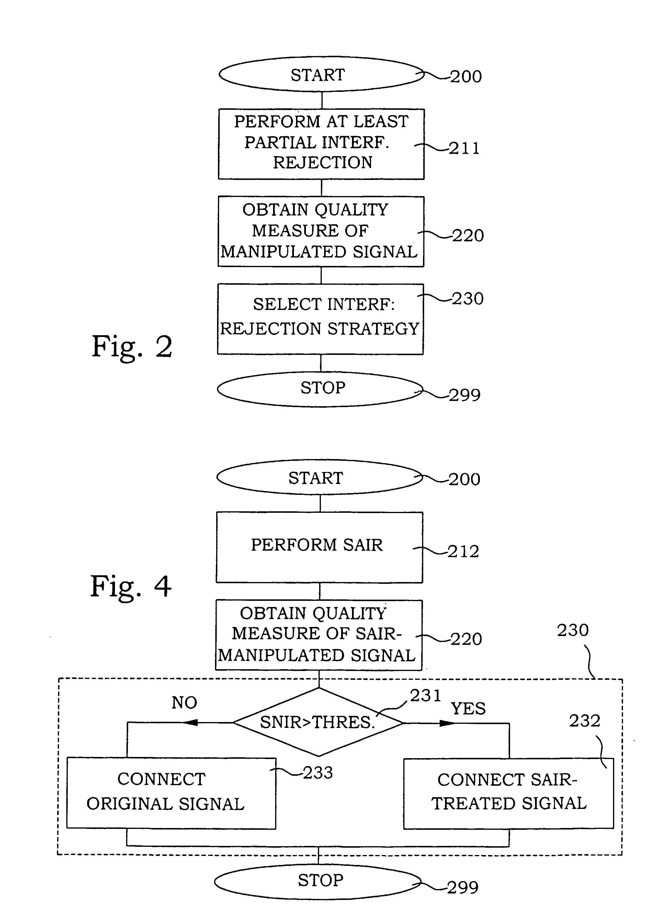
[0035] a receiver 10 according to the present invention is illustrated in FIG. 3. A signal is received in an interference rejection section 11 at a receiving interface 12. The signal is provided to a SAIR section 26, where a SAIR procedure is applied to the received signal. The manipulated signal is provided both to a quality measure detector 16 and a switch 22. The quality measure detector 16 is in this particular embodiment provided with means for estimating a ratio between the signal and the sum of noise and interference.

[0036] The quality measure of the manipulated signals is provided to a decision mechanism 18. In this embodiment, the decision mechanism simply compares the quality measures with a threshold value. If the quality measure is better than the threshold, it is assumed that the interference signal is of e.g. a GMSK type where SAIR is efficient. The decision mechanism 18 sends a control signal to the switch 22, for connection of the manipulated signal terminal accordin...

second embodiment

[0039] a receiver according to the present invention is illustrated in FIG. 5. It resembles the embodiment of FIG. 3 and similar parts are not discussed again. The essential difference is that also the originally received signal is provided to the quality measure detector 16. Subsequently, two quality measures are provided from the quality measure detector 16 to the decision mechanism 18. In the decision mechanism 18, the decision may now instead be based on e.g. the ratio between the quality measures. This means that if the original signal is essentially free from interference, the decision mechanism 18 may control the switch 22 to select the original signal. Any possible deterioration of the original signal is then avoided.

[0040] In the present embodiment, the receiver is furthermore arranged to let the decision mechanism 18 also control 25 the input 27 to the SAIR section 26. This design allows a first decision to be made entirely based on only the quality measure of the original...

third embodiment

[0042] A third embodiment is illustrated in FIG. 7. This embodiment is intended to be used in an EDGE system, where the receiver comprises means for handling GMSK modulation. In an EDGE system, signals of either GMSK- or 8PSK-modulation are present. Furthermore, a training sequence is sent in connection with the digital data. The position of this sequence as well as the content is well known. This fact is used in the present embodiment to reduce unnecessary process power utilization. Instead of performing the “preliminary” interference rejection on the entire signal, the interference rejection is only performed on the training sequence. Furthermore, in this embodiment, the quality measure detector 16 detects the residual error of the signal after channel estimation. (Channel estimation is performed also in connection with the interference rejection.)

[0043] In FIG. 7, the received signal is thus provided to a partial SAIR section 28, where SAIR is employed over only the training sequ...


PUM


Abstract

In the present disclosure, a method / apparatus is provided that detects the impairment in the received signal (12) and employs the structure in the receiver (10) that is designed for that purpose. Preferably, the method / apparatus detects the interferer modulation and employs the structure in the receiver (10) that is designed for that purpose. The detection is preferably performed using a quality measure (16), e.g., the residual errors after channel estimation or SNR (signa-to-noise-ratio) estimates after channel estimation. The present invention involves preferably hypothesis tests, threshold schemes, or schemes where the threshold is adapted according to one of the measures. The operations in the receiver is preferably that is selects between a powerful interference rejection method and a conventional receiver or that is selects between a powerful interference rejection method and a less powerful interference rejection method, or a combination thereof.

Description

TECHNICAL FIELD [0001] The present invention relates in general to methods and devices of digital communication systems, and in particular to interference rejection in such systems. RELATED ART [0002] In most wireless digital communication systems the receivers are designed mainly to combat distortion caused by the communication channel and noise, while the effects of interference are neglected. This causes the receivers to work poorly when the level of interference is high. Many cellular systems are now designed to be interference limited to maximize spectral efficiency. Hence, introduction of receivers with some interference rejection capabilities typically improves the receiver performance. Furthermore, it becomes also possible to tighten the frequency reuse of the system and thereby further increase the system capacity and the spectral efficiency in the systems. [0003] In recent years, receivers that also combat interference have been developed. Several interference rejection te...

Claims


Application Information

Patent Timeline
IPC IPC(8): H04B1/10H04L1/00H04L1/20
CPCH04B1/1027H04L1/0003H04L25/03993H04L1/20H04L1/0021
Inventor OLSSON, MAGNUSARSLAN, HUSEYIN
Owner HIGHBRIDGE PRINCIPAL STRATEGIES LLC AS COLLATERAL AGENT
Learn More