Method for forming a cutting edge along an edge portion of a blade stock

a technology of blade stock and cutting edge, which is applied in the direction of grinding machine components, other manufacturing equipment/tools, manufacturing tools, etc., can solve the problems of increasing drag, unsatisfactory grinding, and negatively affecting the performance of the arrowhead, so as to improve the cutting edge

Inactive Publication Date: 2005-05-26
NEW ARCHERY PRODS
View PDF3 Cites 1 Cited by
  • Summary
  • Abstract
  • Description
  • Claims
  • Application Information

AI Technical Summary

Benefits of technology

[0006] A general object of this invention is to provide an archery arrowhead blade having an improved cutting edge and associated or corresponding methods for making the blade cutting edge.

Problems solved by technology

Additionally, because of its positioning with respect to the blade 2, the cutting wheel 1 typically provides undesirable grinding lines which are generally aligned perpendicular to the edge portion of the blade.
The conventional nonplanar blade surfaces and / or the perpendicular grinding lines can negatively effect the performance of the arrowhead by increasing drag and / or frictional interference.

Method used


Image

  • Method for forming a cutting edge along an edge portion of a blade stock
  • Method for forming a cutting edge along an edge portion of a blade stock
  • Method for forming a cutting edge along an edge portion of a blade stock

Examples


Embodiment Construction

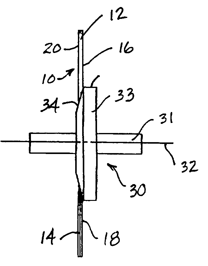
[0030] This invention is directed to a method for forming a cutting edge 14 along an edge portion 12 of a blade stock 10. Blade stock 10 comprises a first blade surface 16 and an opposing second blade surface 20. A first cutting surface 18 is formed on first blade surface 16 and a second cutting surface 22 is formed on second blade surface 20, which intersects first cutting surface 18 to form cutting edge 14 along edge portion 12. Preferably, blade stock 10 is made of a suitable metal material. Other materials suitable for blade stock 10 include, but are not limited to, alloys, plastics, graphite materials and different metal and / or non-metal composite materials.

[0031] Although the various aspects and embodiments of this invention will be described in the context of an archery arrowhead, and more particularly described, without limitation and by way of illustration only, in the context of an archery arrowhead blade 100, it is apparent that the methods of this invention are equally ...


PUM

PropertyMeasurementUnit
acute angleaaaaaaaaaa
perpendicular angleaaaaaaaaaa
angleaaaaaaaaaa

Abstract

A method for forming a cutting edge along an edge portion of a blade stock, wherein the method includes moving the blade stock with respect to a first cutting element rotating about a first rotational axis, the first rotational axis forming one of an acute angle and a perpendicular angle with respect to the cutting edge, and contacting the edge portion and the first cutting element and forming a first cutting surface along the edge portion. The method may also include moving the blade stock with respect to a second cutting element rotating about a second rotational axis, the second rotational axis forming one of an acute angle and a perpendicular angle with respect to the cutting edge, and contacting the edge portion and the second cutting element and forming a second cutting surface along the edge portion so that the second cutting surface intersects the first cutting surface to form the cutting edge. In one embodiment of this invention, at least one of the first rotational axis and the second rotational axis is oriented in a skewed position with respect to a line of the edge portion or a line tangent to an arc segment of the edge portion.

Description

BACKGROUND OF THE INVENTION [0001] 1. Field of the Invention [0002] This invention relates to a method for forming a cutting edge along an edge portion of a blade stock. More specifically, this invention relates to a method for forming a cutting edge on an edge portion of an arrowhead blade having a first cutting surface and a second cutting surface intersecting the first cutting surface to form the cutting edge. [0003] 2. Description of Related Art [0004] Conventional methods for forming a cutting edge along an edge portion of a blade typically includes passing a blade through a grinding apparatus having two opposing grinding wheels. Each grinding wheel rotates about an axis that is generally parallel to the edge portion of the blade on which the cutting edge is formed. For example, as shown in FIGS. 1-4, a cutting wheel 1 may be positioned with respect to the blade 2 and rotatable about a rotational axis 3. The cutting wheel 1 contacts the blade surface as it rotates about the rot...

Claims


Application Information

Patent Timeline
Patent Type & Authority Applications(United States)
IPC IPC(8): B24B3/60
CPCB24B3/60
Inventor MIZEK, ROBERT S.HARWATH, FRANK A.SIMO, MIROSLAV A.
Owner NEW ARCHERY PRODS
Why Eureka
Try Eureka