
Cutting Blade

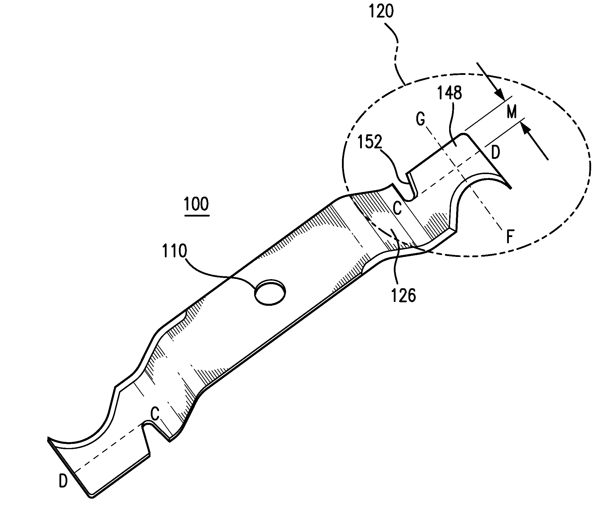
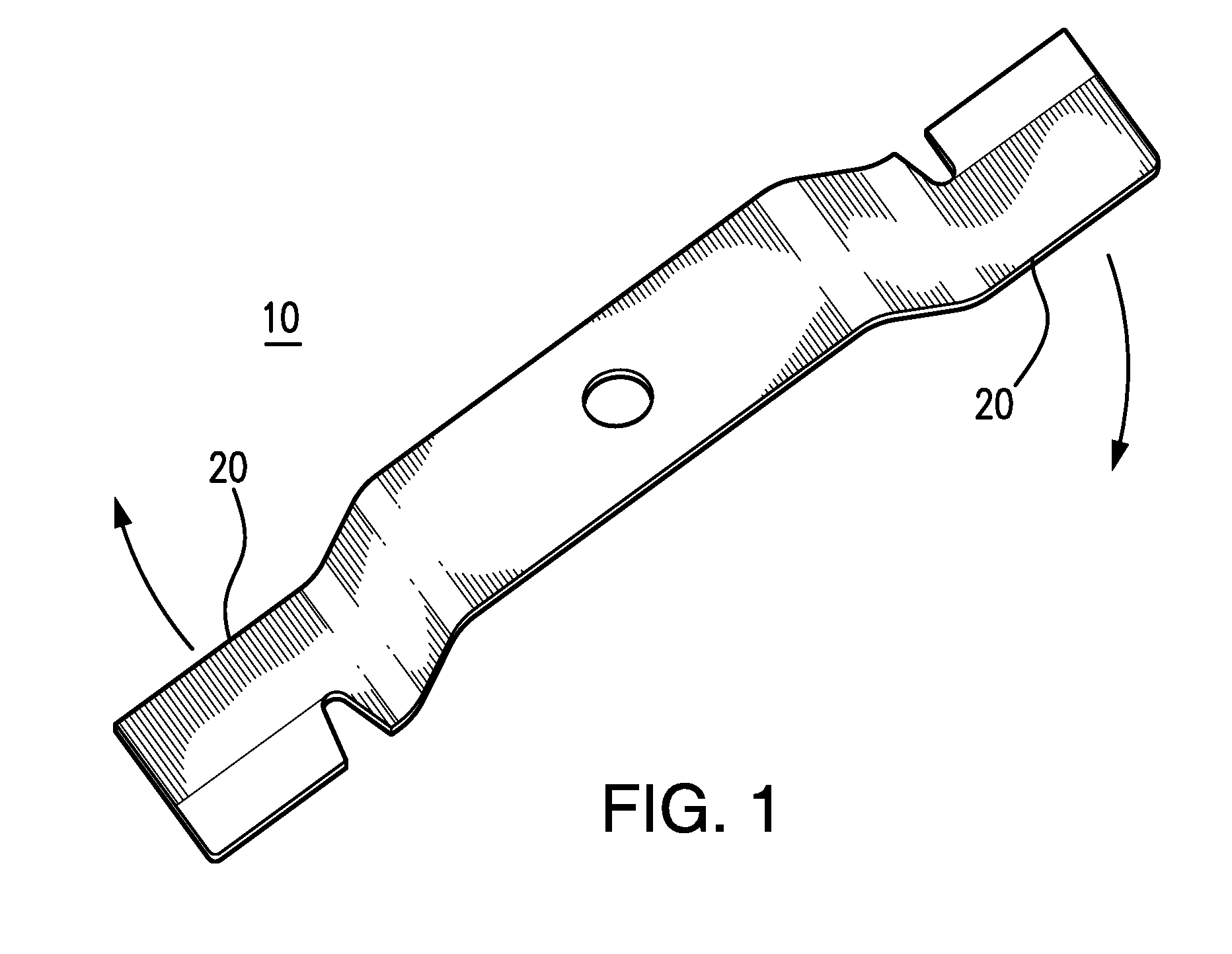
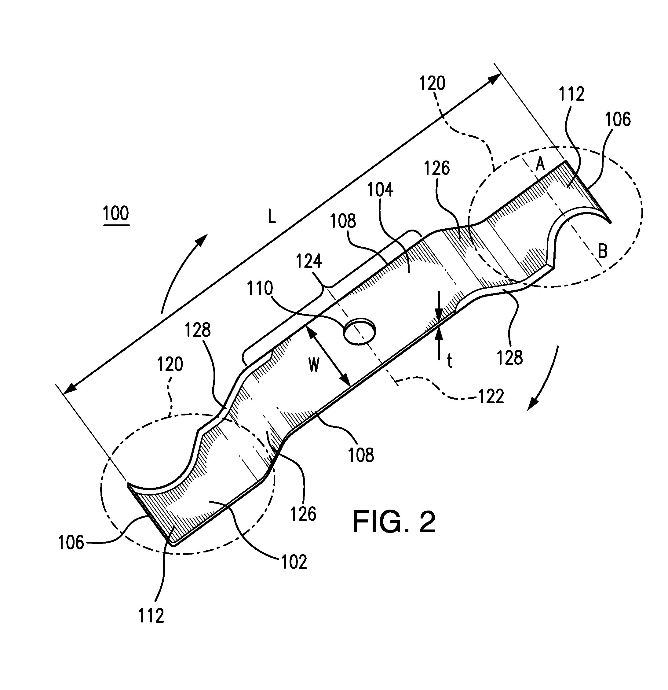
a cutting blade and blade technology, applied in the field of cutting blades, can solve the problems of insufficient design of rotary mowers, insufficient angle of attack, and efforts that fail to provide a complete solution to problems, etc., to achieve the effect of improving cutting edge, improving efficiency, and being convenient to manufacture and maintain

Inactive Publication Date: 2014-07-03
VON RENTZELL WILLIAM E
View PDF5 Cites 20 Cited by
  • Summary
  • Abstract
  • Description
  • Claims
  • Application Information

AI Technical Summary

Benefits of technology

The patent describes an improved rotary lawn mower blade that has a sharper, arc-shaped cut-out at the outer end, allowing for more efficient cutting with a slicing motion. This results in cleaner and more complete cutting of grass, reducing the likelihood of dying or turning brown. Additionally, the blade design reduces the moment of inertia, which leads to lower power consumption and increased efficiency in battery-operated lawn mowers. The patent also provides a cost-effective manufacturing process for the improved blade.

Problems solved by technology

There is a basic deficiency in the design of rotary mowers.
The angle of attack is extremely inefficient, as it is more like a chopping action than a slicing action.
As can be seen, these efforts fall short of providing a complete solution to the problems confronted and solved by the instant disclosure.
Thus, a problem associated with blades that precede the present disclosure is that they do not provide, in combination with the other features and advantages disclosed herein, a blade that slices, rather than chops, through grass to be cut.
Still a further problem associated with blades that precede the present disclosure is that they do not provide, in combination with the other features and advantages disclosed herein, a blade that cuts efficiently and is therefore especially suited for use in battery powered lawn mowers, which tend to have limited use time between charges and thus will more freely benefit from extended run times with a more efficient blade design.
Another problem associated with blades that precede the present disclosure is that they do not provide, in combination with the other features and advantages disclosed herein, a blade that has a reduced moment of inertia, thus requiring less energy to rotate the same at a given rate of speed.

Method used


Image

  • Cutting Blade
  • Cutting Blade
  • Cutting Blade

Examples


Embodiment Construction

[0040]Introduction:

[0041]There is a basic deficiency in the design of rotary mowers. It lies in the blade design and, in particular, in the way in which standard blades attack the grass. The angle of attack is extremely inefficient, as it is more like a chopping action rather than a slicing action. This can be appreciated when considering work with a kitchen knife. Slicing, or stroking the blade edge across the material to be cut, accomplishes the task of cutting with great energy savings over classic “chopping,” or driving the edge through the material to be cut in a straight downward stroke.

[0042]A chopping motion is the cutting approach used by all current rotary mowers. Their cutting edges are driven into the material, much as one drives an axe into a tree trunk. This inefficiency is demonstrated in analogous fashion by two different mandolin slicers; one having a blade edge extending perpendicular to the stroke of the material across the slicer and the other having a blade edge...


PUM


Abstract

An improved blade is disclosed. The blade has an elongated member having rotational symmetry about a center axis. The elongated member further has two ends each having a sharpened edge, wherein at least a portion of each sharpened edge comprises a slicing edge configured to intersect a stalk of grass in non-perpendicular relation. The blade is configured so that rotation of the blade causes the slicing edges to come into non-perpendicular contact with the grass, thereby slicing the grass to be mowed.

Description

CROSS-REFERENCE TO RELATED APPLICATIONS[0001]This application relates to and claims priority from U.S. Provisional Patent Application Ser. No. 61 / 747,649, filed Dec. 31, 2012.FIELD OF THE INVENTION[0002]An improved cutting blade is disclosed. In a preferred embodiment, the improved blade has two-fold rotational symmetry and sharpened, hook shaped cut-outs at the leading edges. These sharpened hook-shaped cut-outs serve to improve cutting efficiency not only by slicing, rather than chopping, through the grass as it cuts, but also by lowering the moment of inertia of the rotating blade and thereby reducing the energy needed to spin the lawn mower blade. The hook-shaped cut-outs may be added to any existing lawn mower blade design. In a second preferred embodiment, the improved blade has upturned sections on the trailing edges. These upturned edges serve to guide grass clippings up and out of the mower.BACKGROUND OF THE INVENTION[0003]There is a basic deficiency in the design of rotary...

Claims


Application Information

Patent Timeline
Patent Type & Authority Applications(United States)
IPC IPC(8): A01D34/64
CPCA01D34/73
Inventor VON RENTZELL, WILLIAM E.
Owner VON RENTZELL WILLIAM E
Learn More