Cutting tool and method for its manufacture

a technology of cutting tools and cutting edges, applied in the field of cutting tools, can solve the problems of increasing susceptibility to cracking, cutting edge abraded, cutting tools worn down in the cutting edge region, etc., and achieves the effect of improving the sharpness and quality of the cutting edge, improving the precision of the cutting edge coating and positioning, and adjusting the radial position of the cutting edg

Active Publication Date: 2017-05-18
KENNAMETAL INC
View PDF10 Cites 0 Cited by
  • Summary
  • Abstract
  • Description
  • Claims
  • Application Information

AI Technical Summary

Benefits of technology

[0010]A significant advantage of the invention exists in particular in that the cutting edge, i.e. a sharp contour, is not formed until after the coating and that, as a consequence, the formation of a cutting edge is independent of the coating process. This advantageously makes it possible to form a cutting edge that is sharper than that in a traditional manufacturing process. In particular, the quality of the cutting edge, i.e. its sharpness, is advantageously independent of the underlying shape of the substrate, since the sharpening—and thus the definition of the cutting edge—only occurs subsequently. This in particular also ensures a precise adjustment of the radial position of the cutting edge.
[0011]This is based on the knowledge that the coating is generally applied approximately uniformly, and therefore substantially follows the outer contour of the substrate. For this reason, with conventional tools the substrate is appropriately prepared and pre-ground or pre-sharpened in order to still subsequently obtain a sufficiently sharp cutting edge even after the coating. According to the present invention, such a preceding sharpening of the substrate is preferably dispensed with at least to such a degree that no full sharpening takes place. Expediently, however, the substrate is pre-sharpened prior to the coating in order to subsequently achieve an improved precision in the coating and positioning of the cutting edge so that in particular the desired final contour, i.e. in particular the sharp cutting edge, is also reliably recovered in the coating, which generally cannot be formed with any thickness. According to the present invention, the cutting edge is thus formed only or at least predominantly via a finishing sharpening step and directly on the coating. A considerably better sharpness and quality of the cutting edge is thereby achieved than by the preceding sharpening and subsequent coating. The cutting tool manufactured accordingly is clearly manufactured more precisely and also has an improved service life as a result of the improved cutting edge.
[0012]Another advantage of the invention exists in particular in that the cutting tool is manufactured with an improved tolerance. This in particular means that the cutting tool has a nominal diameter with a tolerance, and that the coating has a layer thickness, wherein the tolerance is independent of the layer thickness. Generally, the tolerances in the sharpening of the substrate and the application of the coating are added together in the manufacturing. According to the present invention, however, the subsequent processing of the coating by sharpening of the same constitutes an in particular final method step, at least with respect to the design of the outer contour of the cutting tool, so that the tolerance of the nominal diameter is advantageously only determined by the subsequent processing, i.e. the formation of the sharp cutting edge.
[0013]In addition, greater layer thicknesses can thereby also be achieved, since the undesired round edge at the cutting edge, which is traditionally associated with greater layer thicknesses, is precisely avoided. Furthermore, the layer thickness tolerance in particular increases with the layer thickness itself, i.e. tools with thicker layers have a less precise diameter. By means of the subsequent machining, such inaccuracies are also advantageously reduced. This also reduces the risk of micro-cracks in the region of the cutting edge, which also allows greater layer thicknesses and thus a longer service life.
[0014]In a preferred embodiment, the cutting tool is manufactured with a nominal diameter by providing the substrate initially with a substrate diameter that is less than the nominal diameter. The nominal diameter is subsequently adjusted by reducing the coating, in particular by partially grinding it off, in the cutting region after the substrate is coated. The coating is thus reduced by removal or reduction in particular in the radial direction, such that the cutting tool has a specified and desired nominal diameter. By means of the subsequent reduction, the cutting tool is manufactured particularly precisely and has an accordingly improved tolerance.
[0015]As a result of the improved tolerance and the increased precision in the manufacturing in general, the cutting tool is in particular suitable for the final machining of a workpiece, i.e. for treating its surface, for example, during what is known as finishing. In a preferred embodiment, the cutting tool is therefore designed as a finishing tool and in particular as a reamer. The reamer generally comprises a base body with a number of cutting edges that are arranged distributed in particular in the peripheral direction around the base body. A reamer serves primarily for the final machining of boreholes or inner surfaces. The cutting edges therefore generally extend in the longitudinal direction along the base body and up to the end surface, where often times a chamfer or a cutting corner is respectively also arranged in order to ensure a defined transition from the lateral region to the end region.

Problems solved by technology

When the workpiece is machined, the cutting edge is abraded and the cutting tool is worn down in the region of the cutting edge.
With such hard material coatings, there is however the problem that the susceptibility to cracking increases with increasing layer thickness, in particular in the region of the sharp cutting edge.
Higher layer thicknesses in the region of the cutting edge also result in undesired round edges, since the material (that is typically applied using the PVD or CVD method) is increasingly deposited on the edge.
In particular in the region of the cutting edge, there is therefore also the risk of micro-cracks in the coating and it chipping off of the base substrate.

Method used


Image

  • Cutting tool and method for its manufacture
  • Cutting tool and method for its manufacture

Examples


Embodiment Construction

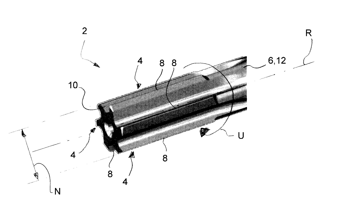
[0019]Generally, the cutting tool comprises a base body or support, on which the cutting region is arranged or formed. In a first variant, the cutting tool is designed as one piece and the base body constitutes the substrate for coating. Prior to coating, cutting regions are then typically ground, for example, into this base body. In a second variant, one or more cutting regions are secured, e.g. soldered or adhesively bonded, on a base body, or alternatively they are secured on a support so as to be removable, as cutting inserts or cutting plates within the meaning of a modular tool. The cutting regions are then coated before or after the mounting on the support or base body and sharpened before or after the mounting.

[0020]The cutting region is thus that part of the cutting tool in which the cutting edge is formed. In doing so, the cutting tool can also comprise several cutting regions in which at least one cutting edge is respectively arranged.

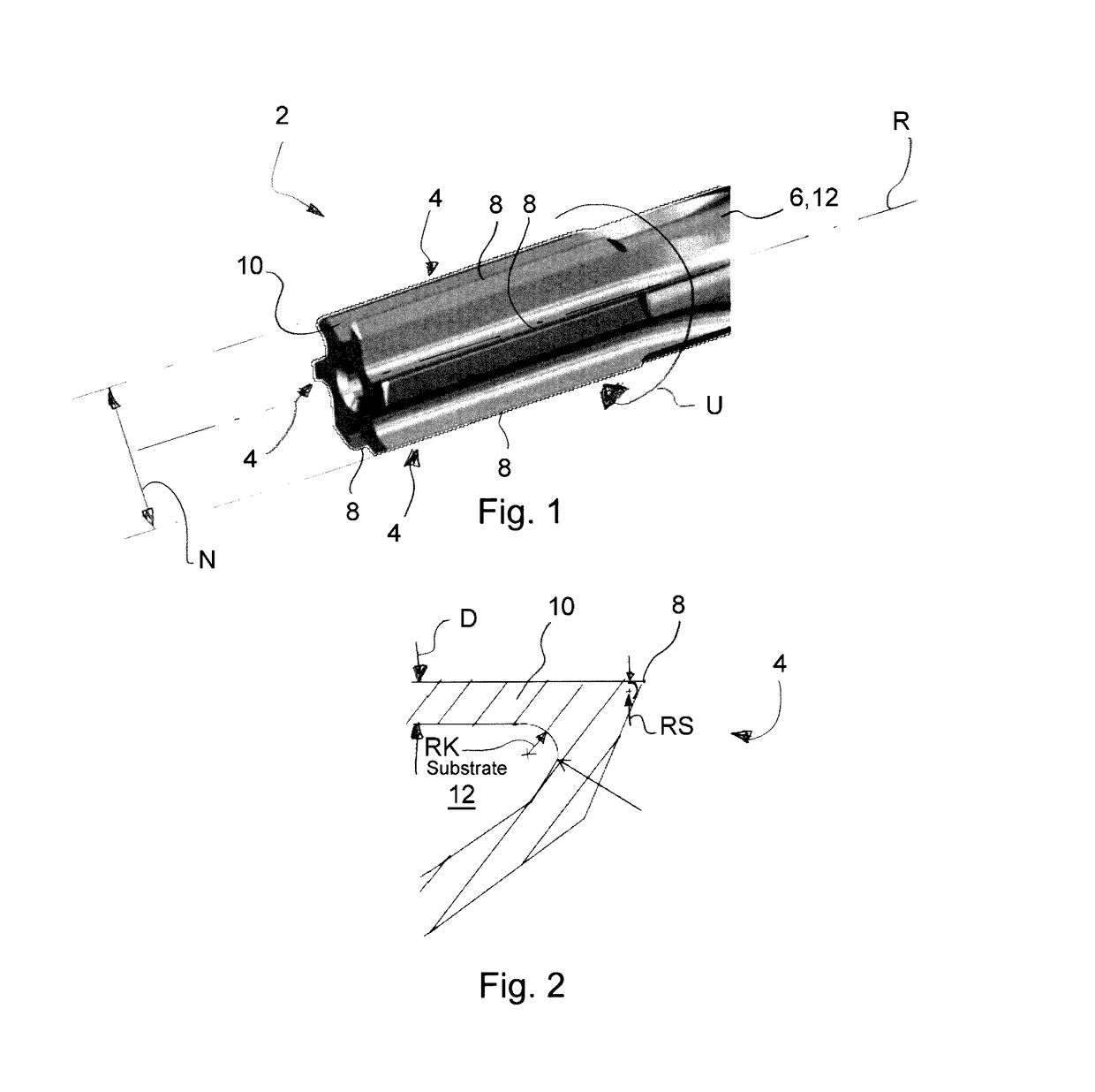
[0021]The substrate generally compris...


PUM

PropertyMeasurementUnit
edge radiusaaaaaaaaaa
cutting edge radiusaaaaaaaaaa

Abstract

A cutting tool (2) is specified with a cutting region (4) that comprises a substrate (12) onto which a coating (10) is applied, which coating (10) is subsequently processed, whereby a sharp cutting edge (8) is formed. Furthermore, a corresponding method for the manufacture of the cutting tool (2) is specified. By means of the sharpening of the cutting edge (8) after the coating rather than before, a particularly sharp cutting edge (8) is formed, whereby the precision of the cutting tool (2) as well as its service life is improved.

Description

RELATED APPLICATIONS[0001]This application claims priority to German Patent Application No. 102015222491 filed Nov. 13, 2015, the contents of which are incorporated herein by reference in its entirety.FIELD OF THE INVENTION[0002]The invention relates to a cutting tool and a method for its manufacture.BACKGROUND[0003]A cutting tool generally serves for machining a workpiece from which material is removed in chips. For this purpose, the cutting tool comprises a number of cutting edges that engage the material. The chips produced are then typically transported away via a flute.[0004]When the workpiece is machined, the cutting edge is abraded and the cutting tool is worn down in the region of the cutting edge. In order to improve the stability of the cutting edge, its cutting properties, and the service life of the cutting tool, it is basically possible to additionally coat them, i.e. to form a cutting edge with a coating made of a hard material. With such hard material coatings, there ...

Claims


Application Information

Patent Timeline
Patent Type & Authority Applications(United States)
IPC IPC(8): B23D77/00C23C14/06C23C14/24B23P15/46B24B3/60
CPCB23D77/00B23P15/46B23D2277/2414C23C14/24C23C14/0641B24B3/60B23B27/00B23B27/14B23C5/16
Inventor HACKER, MICHAELPAUL, MARCUSWENDT, KARL
Owner KENNAMETAL INC
Why Eureka
Try Eureka