Superconducting flywheel main shaft positioning device and using method thereof

A positioning device and spindle technology, applied in the field of high-temperature superconducting flywheel energy storage systems, can solve the problems of the stability and reliability of superconducting flywheels to be improved, and achieve the effect of rapid radial positioning and reduced radial displacement

Pending Publication Date: 2019-08-27
CHINA ELECTRONICS TECH GROUP CORP NO 16 INST
View PDF0 Cites 0 Cited by
  • Summary
  • Abstract
  • Description
  • Claims
  • Application Information

AI Technical Summary

Problems solved by technology

Superconducting flywheel energy storage technology has broad prospects, but the stability and reliability of superconducting flywheel operation still need to be improved

Method used


Image

  • Superconducting flywheel main shaft positioning device and using method thereof
  • Superconducting flywheel main shaft positioning device and using method thereof
  • Superconducting flywheel main shaft positioning device and using method thereof

Examples


Embodiment Construction

[0021] The present invention will be further described below in conjunction with accompanying drawing:

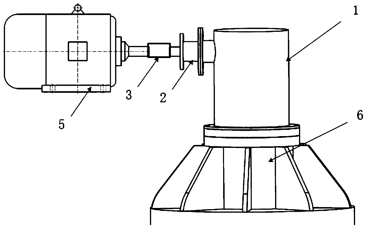
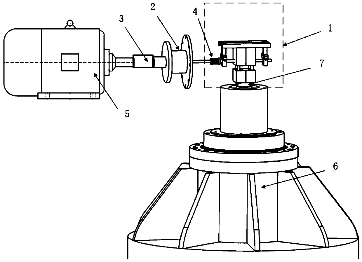
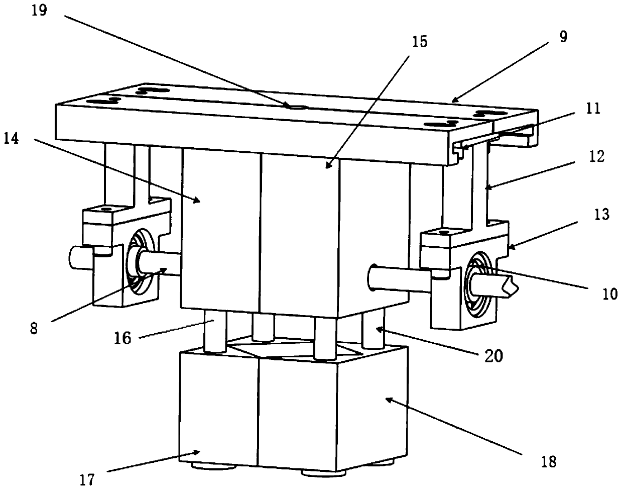
[0022] Such as Figure 1-Figure 3 A superconducting flywheel main shaft positioning device shown includes a vacuum sealed chamber 1 installed above the superconducting flywheel main body, a radial positioning mechanism embedded in the vacuum sealed chamber 1 and a vacuum sealed chamber located on one side of the vacuum sealed chamber 1 The motor 5. Such as figure 1 As shown, the motor 5 is located on the left side outside the vacuum-sealed cavity 1 . The radial positioning mechanism includes a slide rail 9, a left slider 14 and a right slider 15 that are positioned below the slide rail 9 and are slidably engaged with the slide rail 9, pass through the left slider 14 and the right slider 15 in turn, and connect with the left slider The screw rod 8 that block 14 and right slide block 15 are all screw threaded, the left guide rod 16 that is installed in left slide block 14 ...


PUM


Abstract

The invention relates to a superconducting flywheel main shaft positioning device and a using method thereof. The positioning device comprises a vacuum sealing cavity, a radial positioning mechanism and a motor, wherein the vacuum sealing cavity is arranged above a superconducting flywheel host, the radial positioning mechanism is arranged in the vacuum sealing cavity, and the motor is positionedon one side of the vacuum sealing cavity. The radial positioning mechanism comprises a sliding rail, a left sliding block and a right sliding block which are located below the sliding rail and are insliding fit with the sliding rail, a screw rod which penetrates through the left sliding block and the right sliding block in sequence and is in threaded fit with the left sliding block and the rightsliding block, a left guide rod and a right guide rod which are arranged at the bottoms of the left sliding block and the right sliding block respectively, a left clamping block which is arranged on the left guide rod in a sleeved mode and is in clearance fit with the left guide rod, and a right clamping block which is arranged on the right guide rod in a sleeved mode and is in clearance fit withthe right guide rod. The output shaft of the motor is connected with one end of the screw rod. The left clamping block and the right clamping block are provided with clamping grooves respectively. According to the positioning device, the main shaft of the superconducting flywheel can be subjected to reliable, accurate and rapid radial positioning, and the radial displacement caused by axial movement when the flywheel main shaft is in a non-working state is effectively reduced.

Description

technical field [0001] The invention relates to the technical field of high-temperature superconducting flywheel energy storage systems, in particular to a superconducting flywheel spindle positioning device and a method for using the same. Background technique [0002] With the development of the new energy field, energy storage technology has become a worldwide research topic. Among many energy storage technologies, flywheel energy storage has been highly valued at home and abroad for its advantages of high power, high efficiency, long life, high energy storage density, clean and pollution-free. Superconducting flywheel energy storage technology has broad prospects, but the stability and reliability of superconducting flywheel operation still need to be improved. When the superconducting flywheel energy storage device operates under the condition of field cooling, because the pinning effect of the superconducting block needs to capture the magnetic flux, the rotor spindle...

Claims


Application Information

Patent Timeline
Patent Type & Authority Applications(China)
IPC IPC(8): H02K7/02
CPCH02K7/02Y02E60/16
Inventor 杨时红左涛郑旺旺陆勤龙宾峰杨亦霖孙成林刘洋郑婷
Owner CHINA ELECTRONICS TECH GROUP CORP NO 16 INST
Why Eureka
Try Eureka