Static pressure electric spindle headstock clamping device for ultra precision ball bearing ring grinding

A technology of bearing rings and electric spindles, which is applied in the direction of grinding workpiece brackets, grinding machine parts, superfinishing machines, etc., can solve the problems of short fatigue life, easy introduction of vibration, contact wear, etc., and achieve stable radial The effect of positioning, ensuring machining accuracy, and high rotation accuracy

Inactive Publication Date: 2014-10-01
HUNAN HYDRO SPINDLE TECH +1
View PDF6 Cites 0 Cited by
  • Summary
  • Abstract
  • Description
  • Claims
  • Application Information

AI Technical Summary

Problems solved by technology

[0003] The existing bearing ring processing grinding machine generally adopts the clamping structure and method of the bracket and the belt-driven rolling bearing type spindle headstock, which has the following disadvantages: 1. The belt-driven workpiece spindle system will introduce the vibration of the drive motor and the belt system , leading to instability in the grinding process, resulting in grinding vibration marks when grinding the ferrule channel, affecting the processing quality of the channel surface and the error of the roundness of the groove, etc.; 2. The damping and shock absorption performance of the rolling bearing support structure is not ideal , and it is easy to introduce vibration; 3. There is contact wear in the working process of rolling bearings, and the fatigue life is short

Method used


Image

  • Static pressure electric spindle headstock clamping device for ultra precision ball bearing ring grinding
  • Static pressure electric spindle headstock clamping device for ultra precision ball bearing ring grinding

Examples


Embodiment Construction

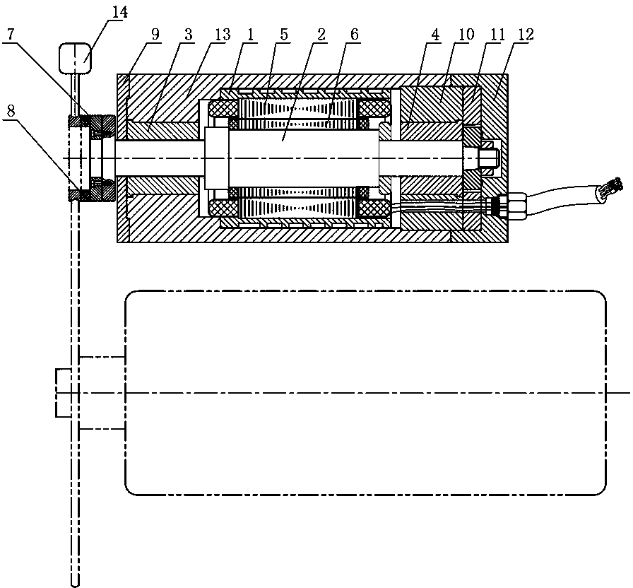
[0016] figure 1 and figure 2 Shown is an embodiment of a static pressure electric spindle headstock clamping device for superfinishing ball bearing ring grinding of the present invention, the device includes a headstock frame 1, a main shaft 2, a front hydrostatic bearing 3, The rear hydrostatic bearing 4, the stator 5 and the rotor 6, the stator 5 is fixed in the head frame frame 1, a water sealing sleeve 13 is provided between the stator 5 and the head frame frame 1, and the rotor 6 is fixedly set on the main shaft 2, The main shaft 2 is set in the head frame frame 1, the position of the rotor 6 corresponds to that of the stator 5, the front end of the main shaft 2 is supported by the front hydrostatic bearing 3, the front end of the front hydrostatic bearing 3 is provided with a front cover 9, and the rear end of the main shaft 2 passes through the rear The hydrostatic bearing 4 is supported, and a rear bearing seat 10 is arranged between the rear hydrostatic bearing 4 an...


PUM


Abstract

The invention discloses a static pressure electric spindle headstock clamping device for ultra precision ball bearing ring grinding. The static pressure electric spindle headstock clamping device comprises a headstock machine base, a spindle, a front hydrostatic bearing, a rear hydrostatic bearing, a stator and a rotor, wherein the stator is fixed in the headstock machine base, the spindle is fixedly sleeved with the rotor, the headstock machine base is sleeved with the spindle, the front end of the spindle is supported through the front hydrostatic bearing, the rear end of the spindle is supported through the rear hydrostatic bearing, a rear bearing block is arranged between the rear hydrostatic bearing and the headstock machine base, a rear end cover is installed at the rear end of the rear hydrostatic bearing, an adjusting pad for adjusting thrust clearance is installed between the rear hydrostatic bearing and the rear end cover, the front end of the spindle extends out of the headstock machine base, a pole mounting base is installed at the front end of the spindle and provided with a pole plate for fixing an ultra precision ball bearing ring, and a support for positioning the ultra precision ball bearing ring in the radial direction is arranged on the periphery of the ultra precision ball bearing ring in front of the pole plate. The static pressure electric spindle headstock clamping device is high in rotation precision, small in end face runout, good in vibration reducing performance and high in processing precision.

Description

technical field [0001] The invention relates to the grinding processing technology of a superfine grinding ball bearing ring, in particular to a static pressure electric spindle head frame clamping device for grinding a superfine grinding ball bearing ring. Background technique [0002] Ultra-precision ball bearings are the core supporting components of high-speed machine tool spindles, aviation gyro systems, navigation systems, aero-engine rotor systems, etc., and their accuracy directly affects the operating accuracy, work efficiency and life of the equipment. To ensure the quality of super-precision ball bearings, the machining accuracy of the inner and outer ring grooves of the bearing must be guaranteed first, including the arc error, roundness, and groove position of the groove. [0003] The existing bearing ring processing grinding machine generally adopts the clamping structure and method of the bracket and the belt-driven rolling bearing type spindle headstock, whic...

Claims


Application Information

Patent Timeline
Patent Type & Authority Applications(China)
IPC IPC(8): B24B41/06B24B19/06
CPCB24B41/04B24B35/00
Inventor 熊万里郑良钢包正江杨明
Owner HUNAN HYDRO SPINDLE TECH
Why Eureka
Try Eureka