Minimally invasive high viscosity material delivery system

a high-viscosity material and delivery system technology, applied in the field of delivery devices, can solve the problems of difficult to deliver to the surgical site using conventional delivery devices such as syringes, high-viscosity materials are difficult to force out of a conventional syringe fitted with a needle, and conventional syringes when used alone (i.e., without needles) are usually too large or too short for insertion into small surgical incisions, and achiev

Inactive Publication Date: 2005-05-26
ISOTIS ORTHOBIOLOGICS
View PDF22 Cites 41 Cited by
  • Summary
  • Abstract
  • Description
  • Claims
  • Application Information

AI Technical Summary

Benefits of technology

[0005] When used properly, the system can reduce the amount of material that would otherwise remain within the delivery system.
[0006] The delivery system, due to its design, is easy to manipulate and to control when dispensing high viscosity material. The system design may also be configured to be low cost and perhaps disposable. This is an advantage when prevention of cross-contamination or a desire for avoiding “clean up” are significant design parameters.

Problems solved by technology

Since the tissue regeneration materials often have high viscosity, they are difficult to deliver to the surgical site using conventional delivery devices such as syringes.
High viscosity materials are difficult to force out of a conventional syringe fitted with a needle.
As a practical matter, conventional syringes when used alone (i.e., without a needle) are usually too large or too short for insertion into small surgical incisions.
Smaller (or “down-sized”) syringes are often difficult to control when applying the high forces necessary to press viscous materials through the small exit bore.
Furthermore, conventional syringes, whether used with or without needles, may be inefficient in that they often retain a portion of the tissue regeneration material inside the syringe body or needle.

Method used


Image

  • Minimally invasive high viscosity material delivery system
  • Minimally invasive high viscosity material delivery system
  • Minimally invasive high viscosity material delivery system

Examples


Embodiment Construction

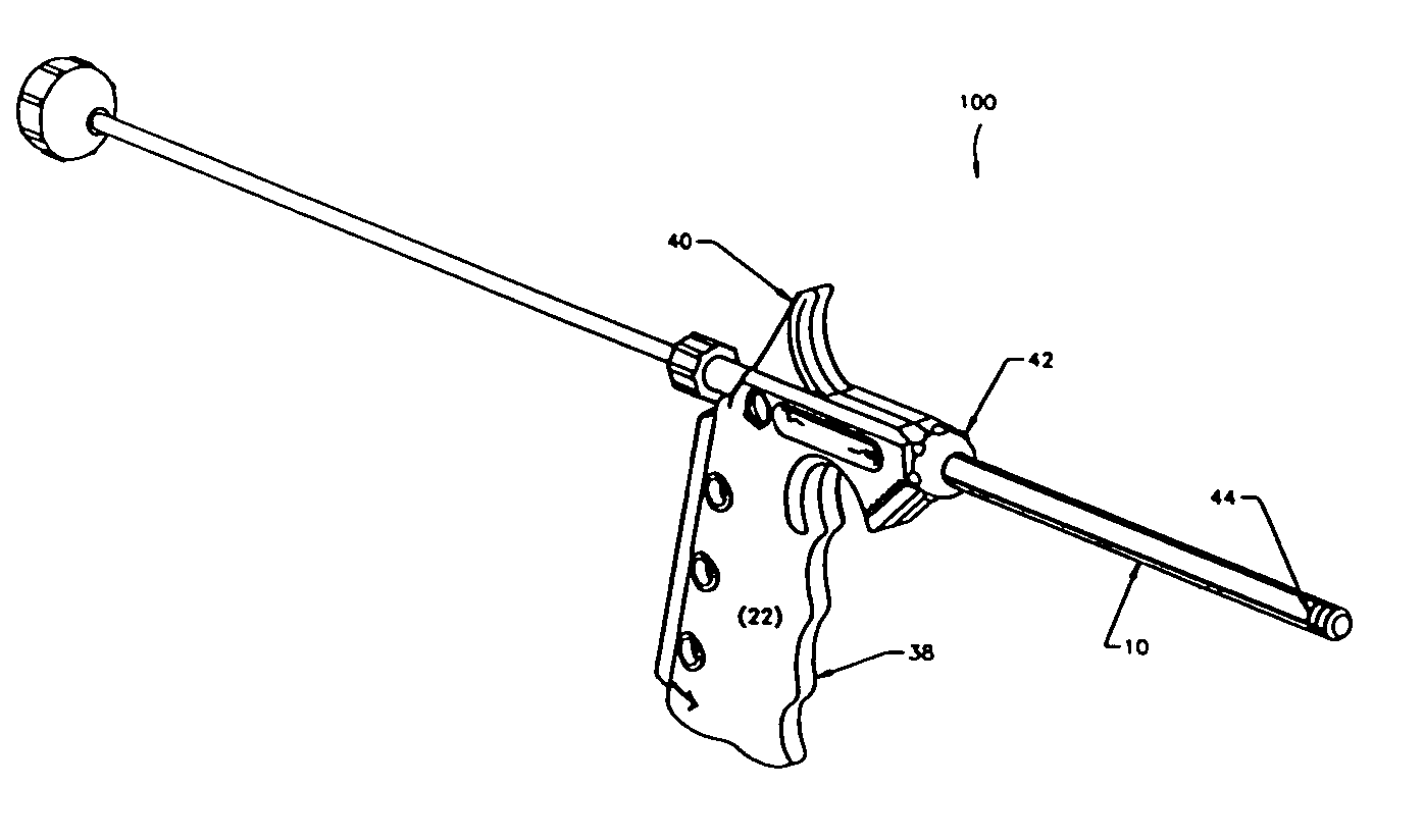
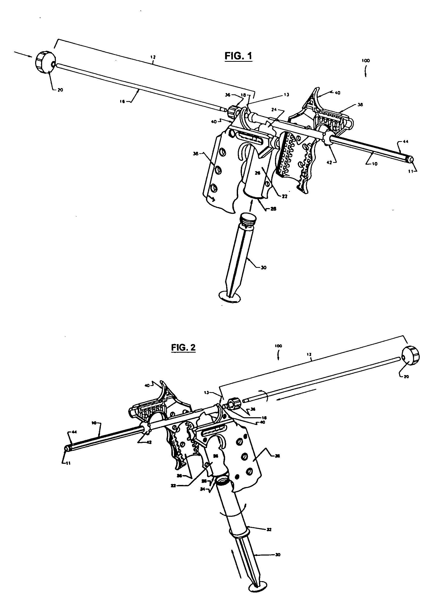
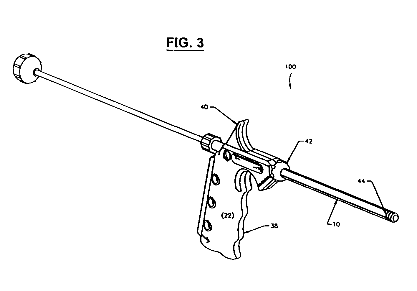
[0011]FIGS. 1-2 show a minimally invasive delivery system 100 for placement of a high viscosity material in the human body. The Figures show a system comprising a cannula 10 that dispenses a high viscosity material 14 (not shown) from an open delivery end or orifice 11 to the selected treatment site in the human body. The end of the cannula 10 opposite the delivery end 11 is associated with a dispenser 12. The dispenser 12 is placed so that it pressures the high viscosity material through and out of the cannula 10. The high viscosity material 14 may be a gel, putty, paste, flowable composition containing particulates, high viscosity liquid (e.g., more viscous than water or the like), a combination thereof, or the like. The cannula 10 may be constructed of a suitable material such as metal, metallic alloys, plastics, glass or the like capable of providing the strength needed to safely introduce the high viscosity material into the treatment site. We have found that stainless steel, p...


PUM


Abstract

A minimally invasive high viscosity material delivery system having a cannula associated with a dispenser for dispensing a high viscosity material out of the cannula, a body member having a first opening that is in communication with the cannula, a reservoir for receiving the high viscosity material, and a second opening associated with a transfer member for pushing the high viscosity material from the body member into the cannula via the first opening. The transfer member is in communication with the second opening. The cannula and the body member are connected in a non-linear angle. Also disclosed is a method of using such system.

Description

FIELD [0001] Described herein are delivery devices suitable for introduction of high viscosity materials into the body. More specifically, the described delivery systems are particularly suitable for the delivery of high viscosity materials into constricted areas, and as such, are particularly useful in surgical procedures. BACKGROUND INFORMATION [0002] Tissue regeneration materials may be used to fill bone defects to effect bone grafts. For better and faster recovery, it may be desirable to minimize the size of the surgical incisions required for the delivery of those tissue regeneration materials to the desired site. Since the tissue regeneration materials often have high viscosity, they are difficult to deliver to the surgical site using conventional delivery devices such as syringes. High viscosity materials are difficult to force out of a conventional syringe fitted with a needle. As a practical matter, conventional syringes when used alone (i.e., without a needle) are usually ...

Claims


Application Information

Patent Timeline
Patent Type & Authority Applications(United States)
IPC IPC(8): A61F2/00A61F2/30A61F2/46
CPCA61F2/4601A61F2002/4692A61F2002/4635A61F2002/30601
Inventor KAY, JOHN F.SICKLER, MICHAEL F.
Owner ISOTIS ORTHOBIOLOGICS
Why Eureka
Try Eureka