
Surgical instrument with improved handle assembly

a technology of handle assembly and surgical instruments, applied in the field of surgical instruments, can solve the problems of short lever arms for the maintenance of stability, clip failure to close properly, and easy misalignment of the handle assembly, so as to facilitate the positioning of the fingers, and increase the spacing

Inactive Publication Date: 2005-05-26
APPL MEDICAL RESOURCES CORP
View PDF21 Cites 184 Cited by
  • Summary
  • Abstract
  • Description
  • Claims
  • Application Information

AI Technical Summary

Benefits of technology

[0012] These deficiencies of the prior art are overcome with the present invention which includes a bayonet fitting disposed at the pivot point or fulcrum of the handle assembly. The bayonet fitting not only provides increased stability for the handle assembly, but also facilitates assembly of the handles and subsequent disassembly for cleaning purposes. Upon disassembly, all surfaces are exposed to enhance cleaning of the separate handles of the assembly. Alternatively, a locking pin can be provided to inhibit disassembly when desired.

Problems solved by technology

Unfortunately, with a typical elongate configuration, the handles and jaws are spaced a considerable distance from the pivot point or fulcrum, so that the handle assembly tends to be susceptible to misalignment.
When jaws become misaligned, clips cannot be closed properly and may even fall from the jaws of the assembly.
These hinges provide larger areas of surface contact but unfortunately these areas are fairly close to the fulcrum and therefore offer very short lever arms for the maintenance of stability.
While box hinges have been of some value for stability purposes, they present many hidden surfaces which are not susceptible to cleaning.
Furthermore, the box hinges have functioned as permanent attachments and have not permitted complete separation of the handles.
In a modular system, the disposable cartridge is typically manufactured with molded plastic components which are not particularly amenable to close tolerances.
Especially where complex linkage is involved, the need for plastic parts with closer tolerances can add significantly to manufacturing costs.

Method used


Image

  • Surgical instrument with improved handle assembly
  • Surgical instrument with improved handle assembly
  • Surgical instrument with improved handle assembly

Examples


Embodiment Construction

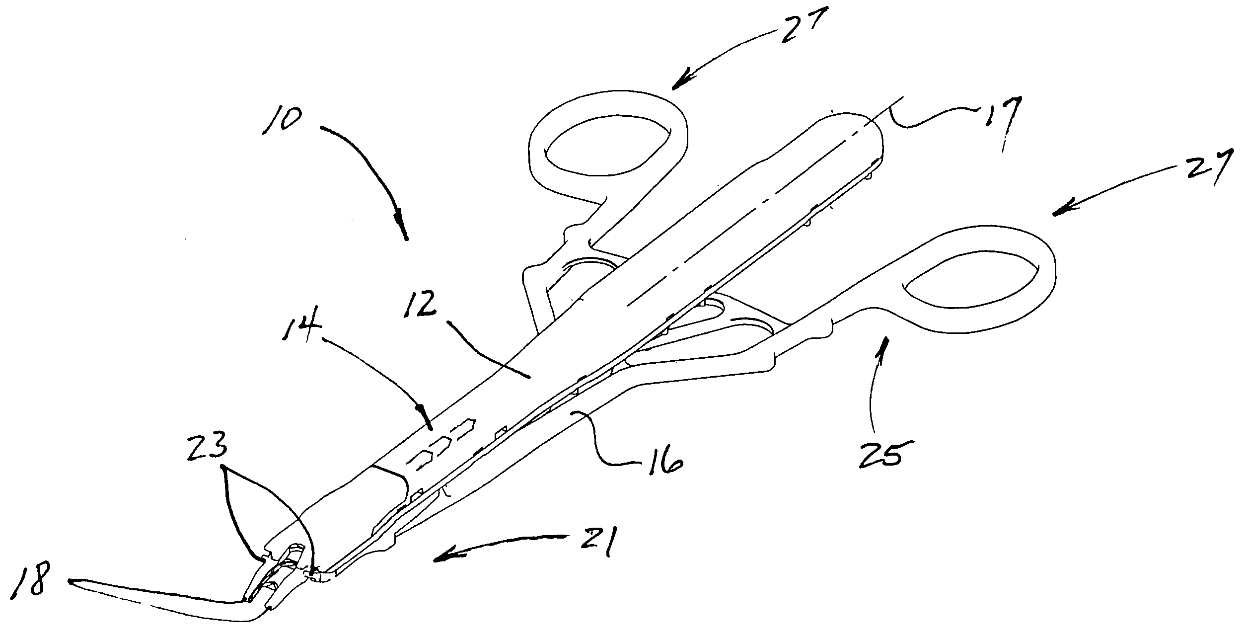
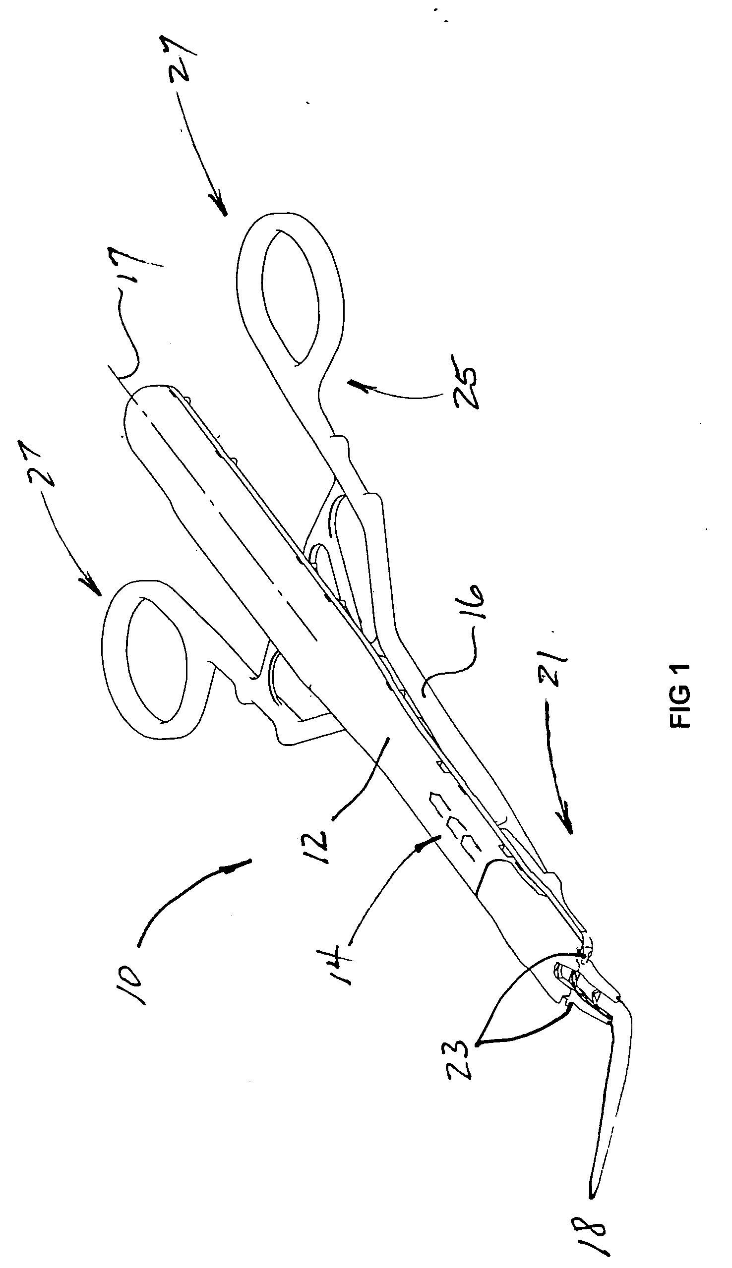
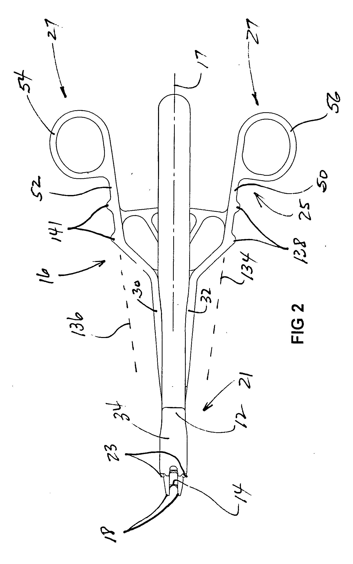
[0049] A modular ligating clip applier is illustrated in FIG. 1 and designated by the reference numeral 10. A cartridge 12 containing a train of ligating clips 14 is removably carried on and operated by a handle assembly 16 having an axis 17. Jaws 18, carried by the cartridge 12, are adapted to receive the clips, one at a time, and to crimp the received clip onto body tissue, such as a blood vessel of a patient.

[0050] Movement of the jaws 18 from the normally opened state to the closed state is accomplished by operation of the handle assembly 16 which, in a preferred embodiment, has a scissors configuration. The handle assembly 16 has a distal end 22 terminating in a pair of pawls 23 and a proximal end 25 terminating in a pair of finger rings 25. The pawls 23 extend outwardly of the jaws 18 and are operable by closing the finger rings 25 to move the jaws 18 from the normally opened position to the closed position.

[0051] A modular ligating clip applier of this type is illustrated a...


PUM

PropertyMeasurementUnit
anglesaaaaaaaaaa
anglesaaaaaaaaaa
relative angleaaaaaaaaaa

Abstract

A modular clip applier includes a cartridge containing multiple surgical clips, and a handle assembly for operating the cartridge to crimp one of the clips onto body tissue of a patient. The handle assembly has a scissors configuration with a bayonet coupling, and flange pairs widely separated to provide a high degree of stability. The bayonet coupling enables the handles of the assembly to be fully separated for cleaning. Snap fittings between the cartridge and handle assembly are provided at the fulcrum and also at a spaced location where an operating pin of the cartridge engages intersecting slots in the flanges. Overdrive protection of three different types is contemplated along with a structure facilitating operation of the handle assembly by palming a pair of handle bars.

Description

CROSS REFERENCE TO RELATED APPLICATIONS [0001] This application claims the priority of U.S. Provisional Application Ser. No. 60 / 117,079 filed on Jan. 25, 1999, and co-pending PCT Application Serial No. PCT / US00 / 01216 filed on Jan. 1, 2000, both of which are incorporated herein by reference.BACKGROUND OF THE INVENTION [0002] 1. Field of the Invention [0003] This invention relates generally to surgical instruments, and more specifically to instruments having such as ligating clip appliers adapted to operate and effectors such as multiple-clip cartridges. [0004] 2. Discussion of Related Art [0005] Surgical instrument clip appliers commonly include handles that are operable by a user to close a pair of jaws. In the case of clip applies, a ligating clip, removably mounted within the jaws, can be crimped or closed to engage tissue or occlude a body conduit such as a blood vessel. The clip is initially mounted within the jaws when the jaws are in an opened state. When the handles are opera...

Claims


Application Information

Patent Timeline
Patent Type & Authority Applications(United States)
IPC IPC(8): A61B17/128A61B17/28
CPCA61B2017/2916A61B17/128
Inventor GADBERRY, DONALD L.KAHLE, HANKJOHNSON, GARY M.ANDERSON, STEVEN R.
Owner APPL MEDICAL RESOURCES CORP
Learn More