Eureka AIR delivers breakthrough ideas for toughest innovation challenges, trusted by R&D personnel around the world.

Bendable extension pipe for vacuum cleaner

Inactive Publication Date: 2005-06-02
SAMSUNG GWANGJU ELECTRONICS CO LTD
View PDF5 Cites 31 Cited by
  • Summary
  • Abstract
  • Description
  • Claims
  • Application Information

AI Technical Summary

Benefits of technology

[0007] Accordingly, the present invention has been conceived to solve the above-mentioned problems occurring in the conventional vacuum cleaners, and an aspect of the present invention is to provide a bendable extension pipe for a vacuum cleaner having an improved construction that permits a user to conveniently perform cleaning operations by simple manipulation of a button without needing to bend the body or lower his or her posture.

Problems solved by technology

In addition, even if the angle between the extension pipe and the suction brush is adjustable, inconvenience results in that the user must lower his / her body in order to insert the suction brush into an area under the furniture.

Method used


Image

  • Bendable extension pipe for vacuum cleaner
  • Bendable extension pipe for vacuum cleaner
  • Bendable extension pipe for vacuum cleaner

Examples


Embodiment Construction

[0019] Hereinbelow, a bendable extension pipe for a vacuum cleaner according to the present invention will be described in detail with reference to the accompanying drawings.

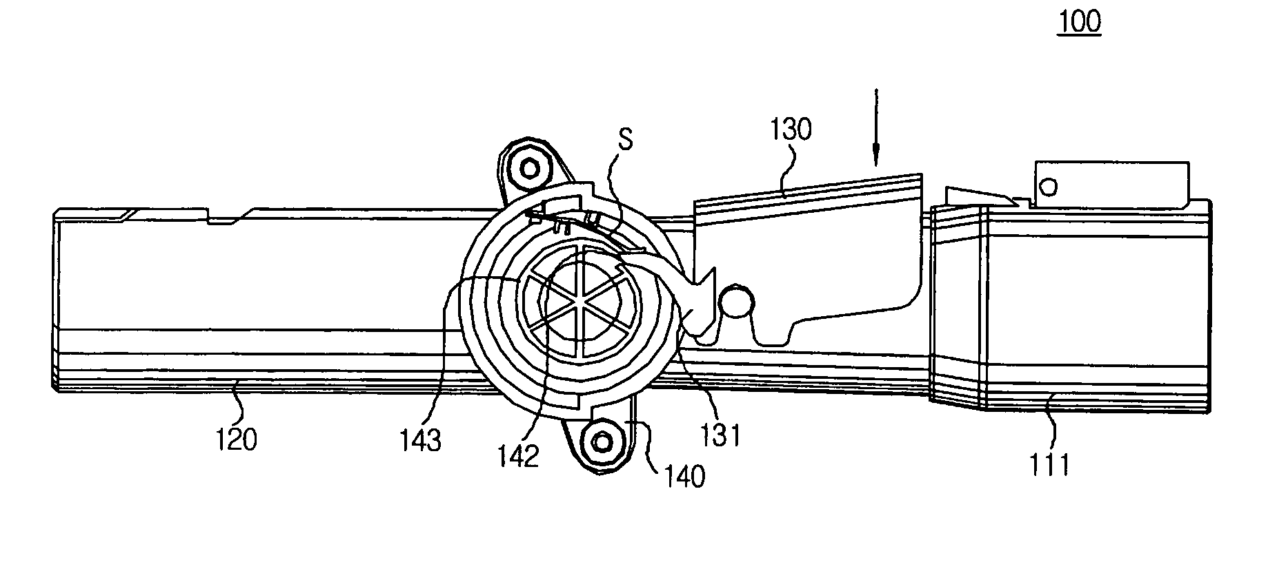
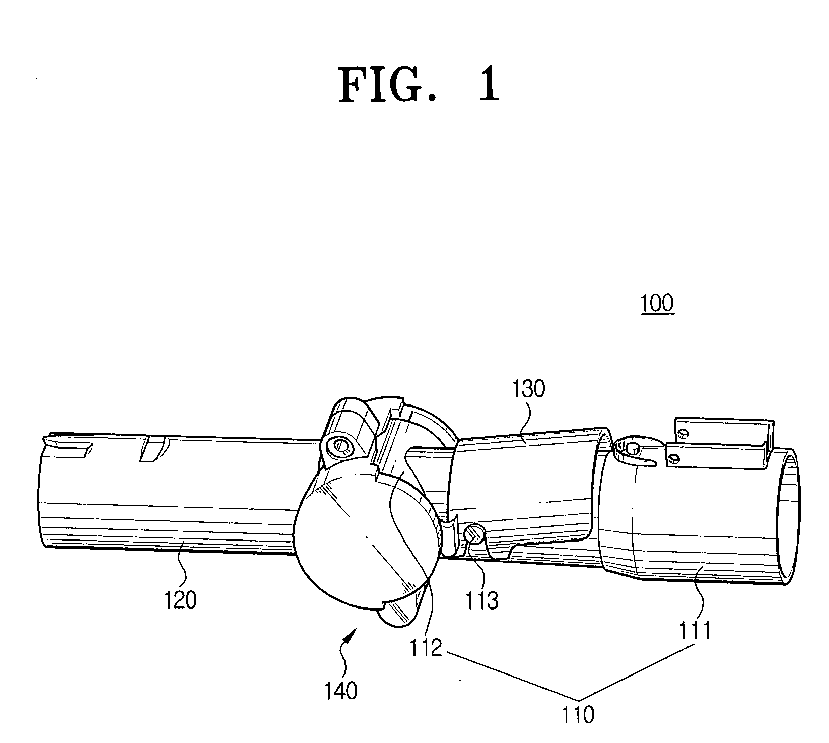
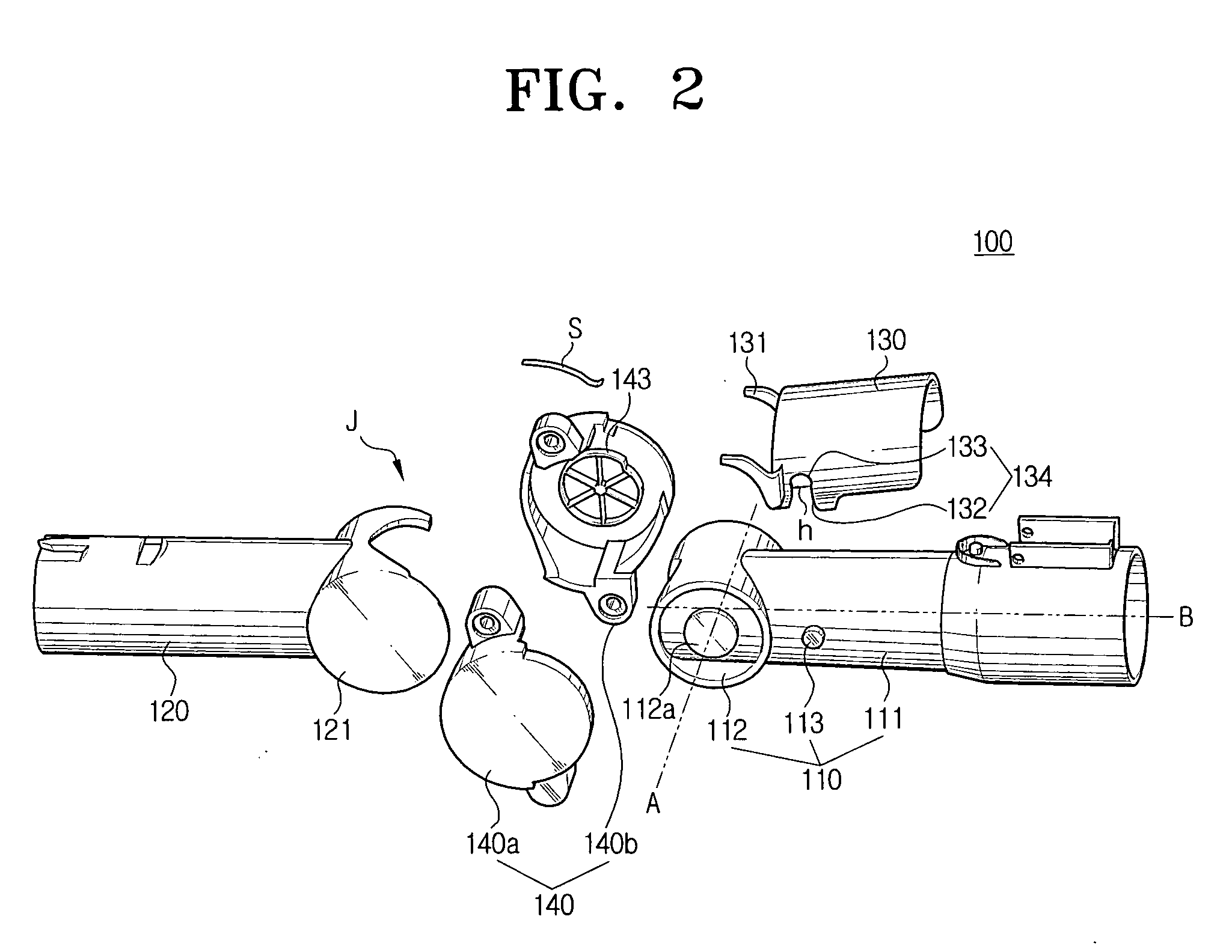
[0020] As shown in FIGS. 1 and 2, a bendable extension pipe 100 comprises a first extension pipe section 110, a second extension pipe section 120, a release handle 130, and an articulated cover 140.

[0021] The first extension pipe section 110 comprises a tubular body 111, a cylindrical joint 112 formed at one end of the body 111, for providing a joint connection of tubular body 111 to the second extension pipe section 120, and hinge projections 113 formed on the body 111 to project outwardly from a surface so as to provide an installation mount for the release handle.

[0022] The cylindrical joint 112 is preferably arranged in such a way that its axis, shown as broken line A in FIG. 2, perpendicularly intersects the virtual central axis, shown as broken line B, of a flow passage formed within the body 111. Protr...


PUM


Abstract

A bendable extension pipe for a vacuum cleaner that comprise at least two sections capable of being bent relative to each other according to user's selection comprising a first extension pipe section; a second extension pipe section pivotably connected to the first extension pipe section; and a release handle selectively for locking the first and second extension pipe sections in a predetermined configuration, wherein the first and second extension pipe sections are released from the locking configuration when a user depresses the release handle.

Description

BACKGROUND OF THE INVENTION [0001] 1. Field of the Invention [0002] The present invention relates generally to a vacuum cleaner and in particular to a bendable extension pipe for a vacuum cleaner, the bendable extension pipe having a joint foldably connected to the vacuum cleaner, thereby permitting convenient cleaning of spaces under pieces of furniture, such as bed or sofa. [0003] 2. Description of the Background Art [0004] In general, a vacuum cleaner draws in contaminants on a surface to be cleaned which are entrained in air drawn in to the vacuum cleaner with the aid of a vacuum suction force generated by a vacuum suction motor provided in a cleaner body. Generally, a flow passage is formed so as to connect the cleaner body and a suction brush used for performing the cleaning operation in and airtight connection. [0005] Such a flow passage may be variously provided depending on the types of vacuum cleaners being used. For example, a canister vacuum cleaner is provided with a fl...

Claims


Application Information

Patent Timeline
IPC IPC(8): A47L9/24F16L27/08
CPCF16L27/0849A47L9/242A47L9/24
Inventor JEON, KYONG-HUI
Owner SAMSUNG GWANGJU ELECTRONICS CO LTD
Why Eureka
Eureka Blog
Learn More