Component mounting apparatus
- Summary
- Abstract
- Description
- Claims
- Application Information
AI Technical Summary
Benefits of technology
Problems solved by technology
Method used
Image
Examples
Embodiment Construction
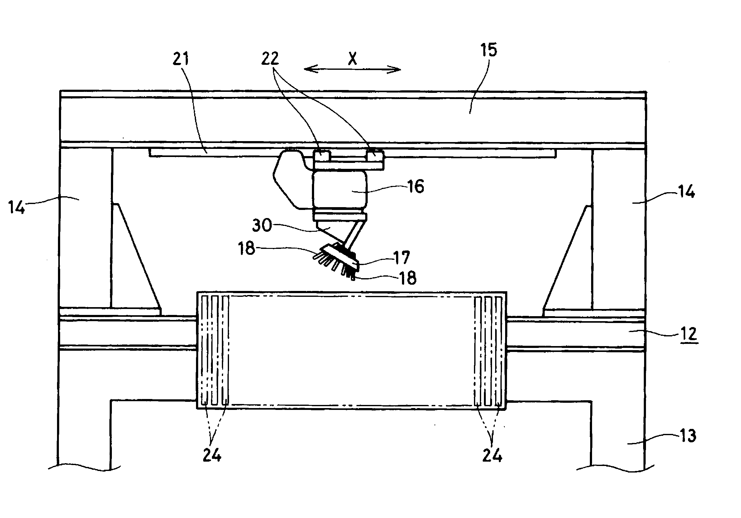
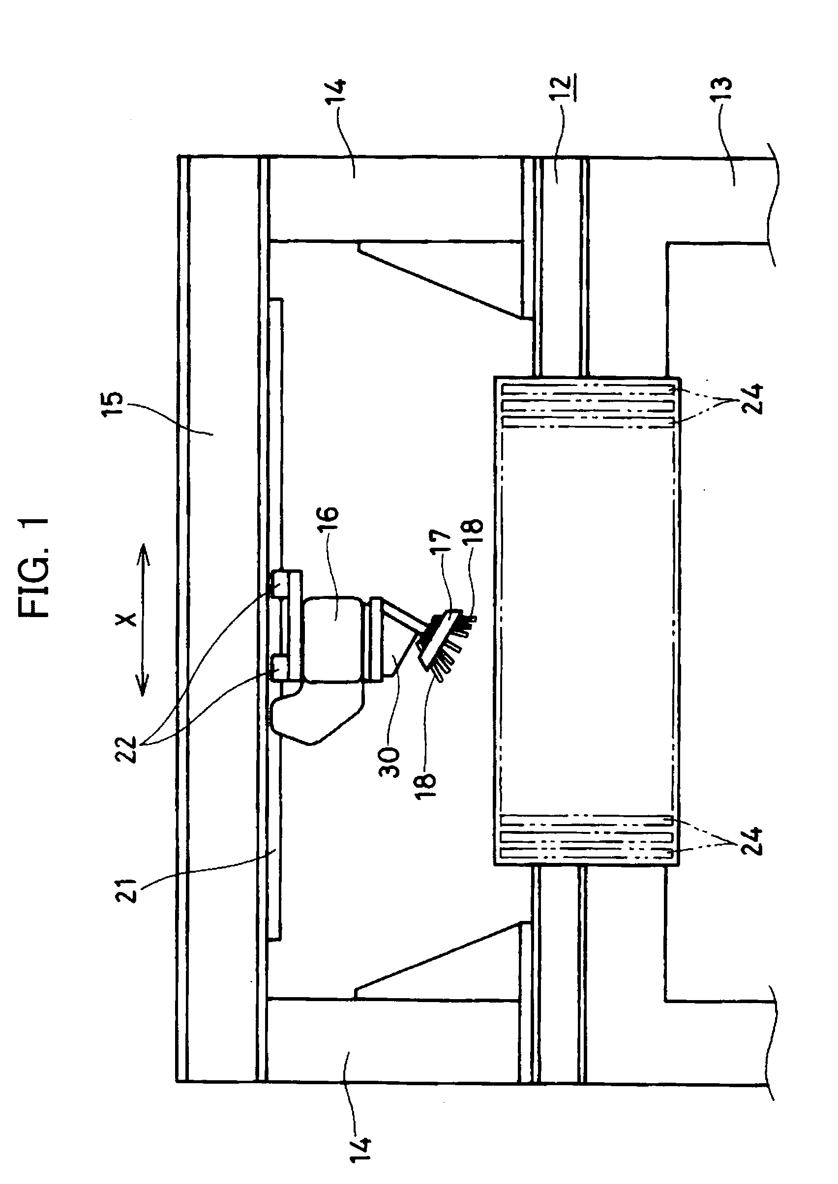
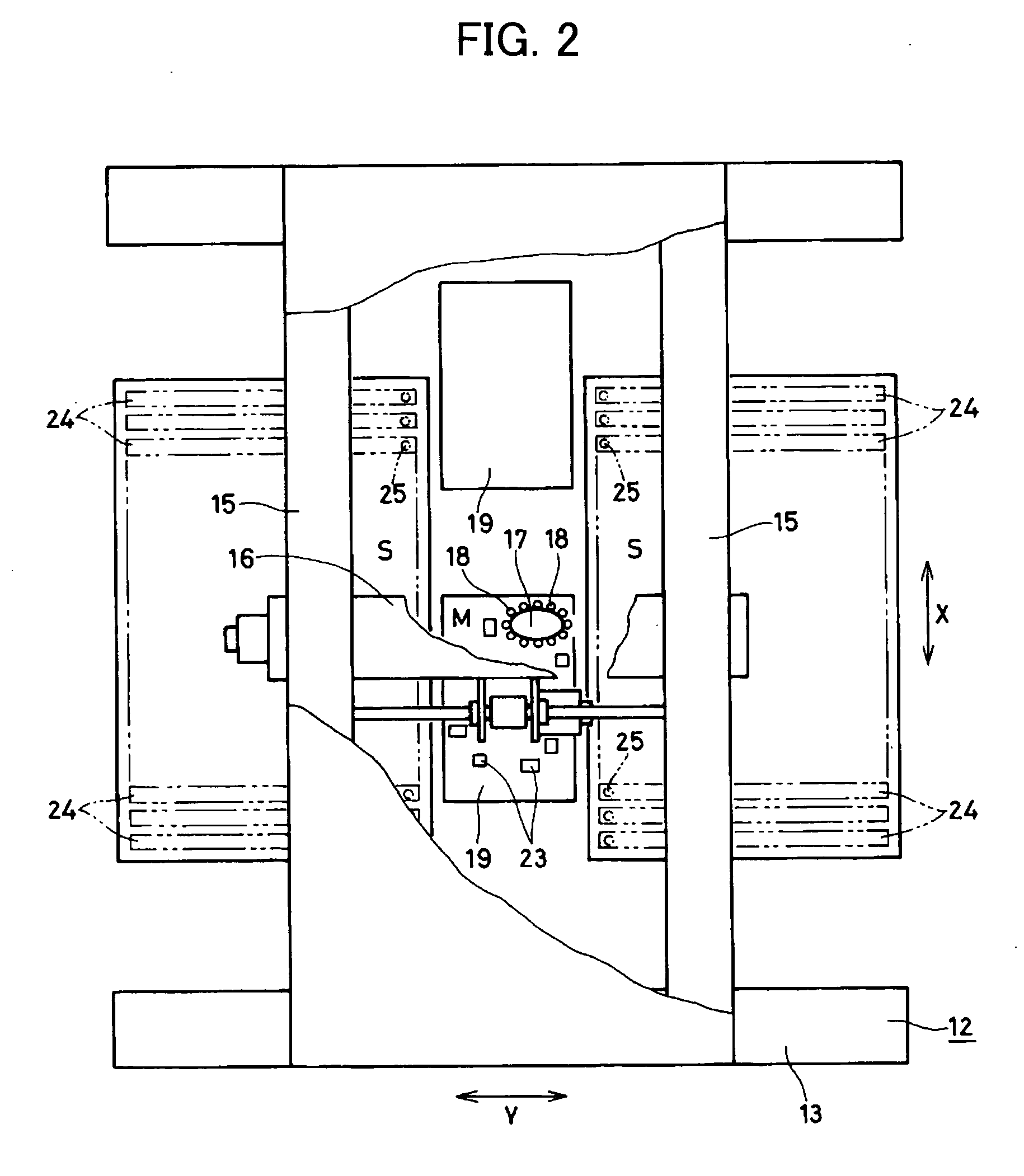
[0051]FIG. 1-FIG. 3 show the whole component mounting apparatus according to a preferred embodiment of the present invention. The component mounting apparatus comprises a base 12, a table 13 for supporting the base 12, four support legs 14 provided at both left and right end portions for supporting both end portions in the forward / backward direction of the table 13, crossbars 15 bridging over the longitudinal direction of the table 13 at the top ends of the pair of support legs 14 separated in the forward / backward direction, a head loading beam 16 bridging between the crossbars 15 in such a manner to depend therefrom, a tool head 17 depending from the head loading beam 16 and a plurality of vacuum pick-up nozzles 18 attached to the tool head 17. It is to be noted herein that the direction as indicated by an arrow X in FIG. 1 and FIG. 2 is referred to as the forward / backward direction or the X-axis direction and the direction as indicated by an arrow Y in FIG. 2 and FIG. 3 is referre...
PUM
| Property | Measurement | Unit |
|---|---|---|
| Vacuum | aaaaa | aaaaa |
Abstract
Description
Claims
Application Information
 - R&D
- Intellectual Property
- Life Sciences
- Materials
- Tech Scout
- Unparalleled Data Quality
- Higher Quality Content
- 60% Fewer Hallucinations
Browse by: Latest US Patents, China's latest patents, Technical Efficacy Thesaurus, Application Domain, Technology Topic, Popular Technical Reports.
© 2025 PatSnap. All rights reserved.Legal|Privacy policy|Modern Slavery Act Transparency Statement|Sitemap|About US| Contact US: help@patsnap.com


