
Case bottom for large caliber ammunition and method for producing same
- Summary
- Abstract
- Description
- Claims
- Application Information
AI Technical Summary
Benefits of technology
Problems solved by technology
Method used
Image

Examples
Embodiment Construction
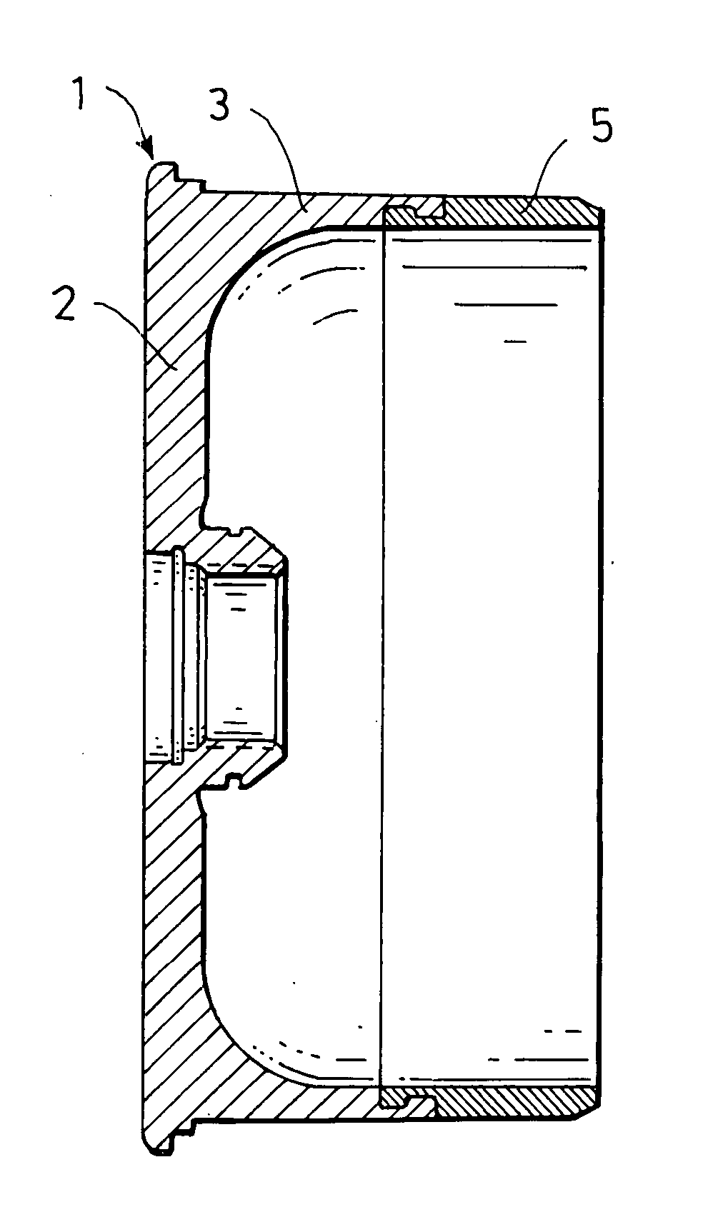
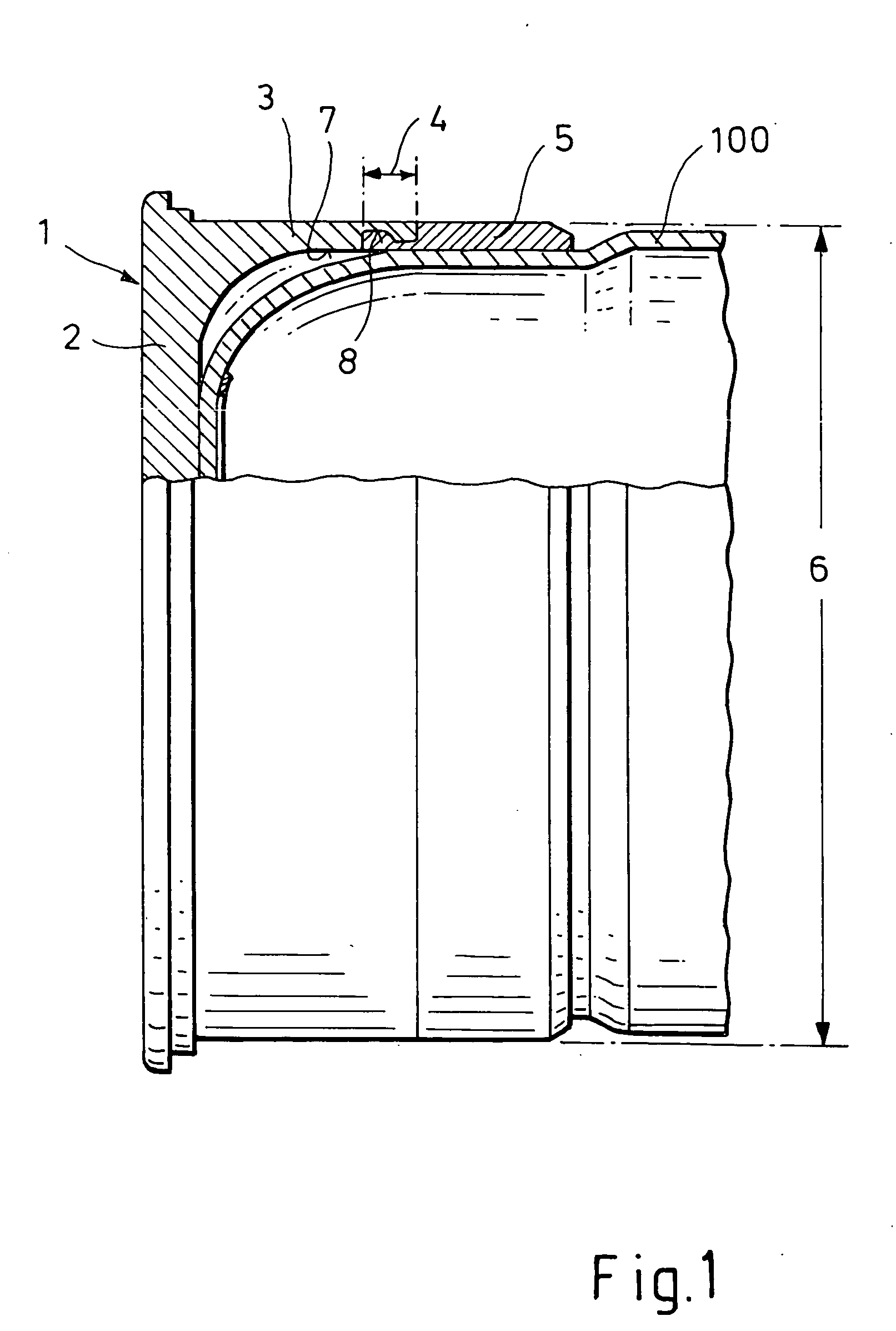
[0019]FIG. 1 shows an example of an embodiment of the invention. The reference 1 in FIG. 1 relates to the case bottom of a tank cartridge with combustible case jacket 100. The case bottom 1 comprises a bottom section 2 and a cylindrical case section 3 of steel. On the side facing away from the bottom section 2, the case section 3 is provided with a guide region 4 for guiding a ring-shaped obturation 5 of rubber that projects on the front and is connected to the case bottom 3.
[0020] According to the invention, the outside diameter 6 of the guide region 4 is selected such that following the loading of the respective cartridge, the guide region supports itself directly and peripherally on the loading chamber inside wall of the respective weapon (not shown herein), so that no plastic deformation can occur in the guide region 4 during the firing of a cartridge.
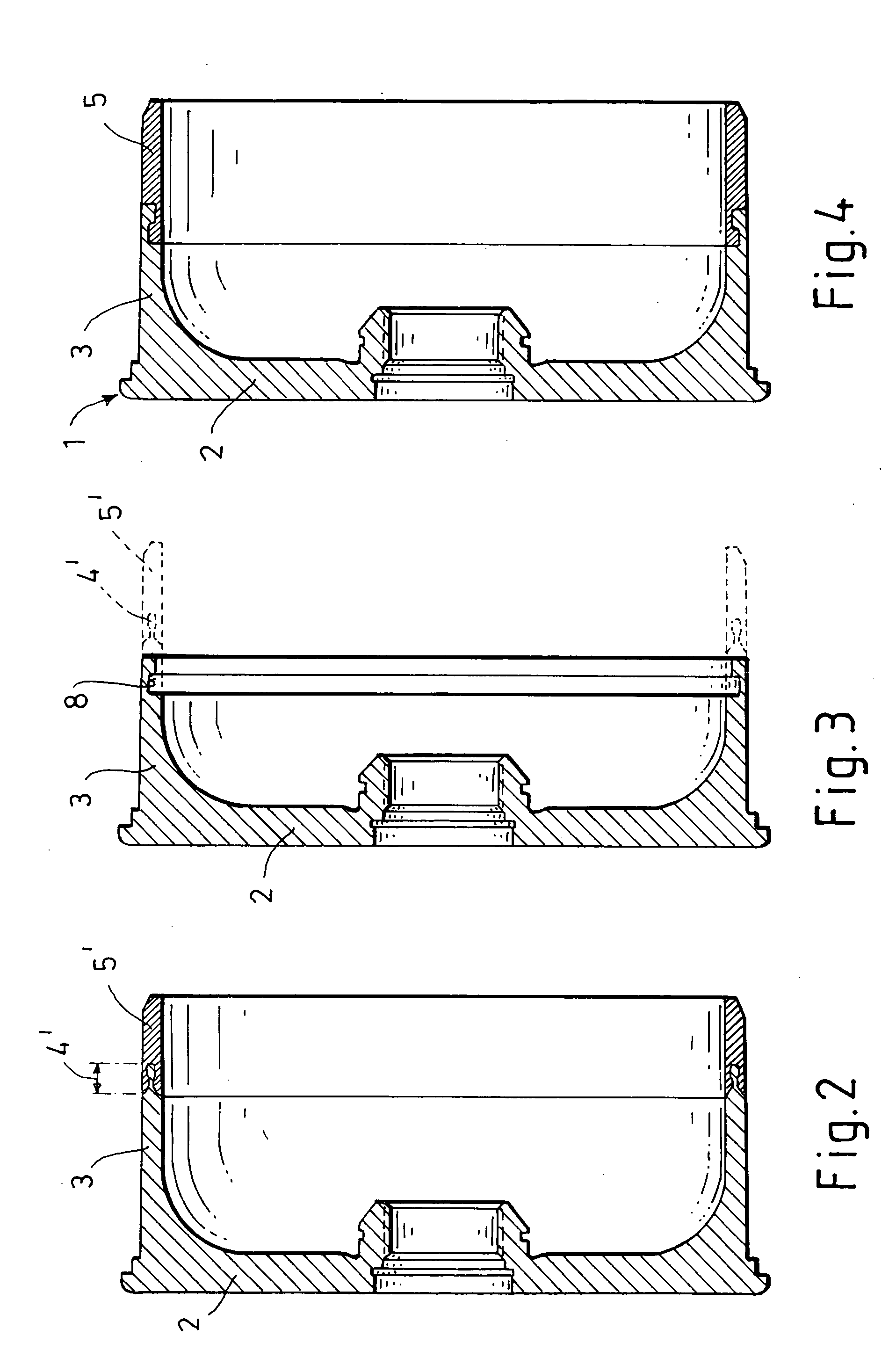
[0021] The internal surface 7 of the case section 3 is provided with an annular groove 8 in the guide region 4, wherein the obt...
PUM
 Abstract
Description
Claims
Application Information