Dual-acting band brake

Inactive Publication Date: 2005-09-27
DEERE & CO
View PDF26 Cites 2 Cited by
  • Summary
  • Abstract
  • Description
  • Claims
  • Application Information

AI Technical Summary

Benefits of technology

[0010]Thus, there is provided a band brake assembly which possesses an ability to resist active and repeated pressures often resulting in fatiguing and failure of the pin or pins when braking is undertaken. Further, there is provided a brake assembly which enables flexibility in the design placement thereof so as to avoid the unnecessary consumption of space which may otherwise affect the design placement of other vehicle components.
[0012]The actuator is constructed with openings at an end thereof through which pins, carrying the band, are inserted so as to allow a majority of the force from the actuator to be placed on the band instead of the pins when the actuator is moved. Accordingly, as the actuator rotates, the pins move with the actuator and serve as carriers of the band permitting them to see substantially low amounts of force since they move in the same direction and with the actuator as braking occurs. Moreover, through connection of both ends of the band with a single cylindrical actuator, the assembly offers increased braking capacity since both ends of the band will be pulled tightly around the drum when braking is attempted.

Problems solved by technology

Thus, there is provided a band brake assembly which possesses an ability to resist active and repeated pressures often resulting in fatiguing and failure of the pin or pins when braking is undertaken.

Method used


Image

  • Dual-acting band brake
  • Dual-acting band brake
  • Dual-acting band brake

Examples


Embodiment Construction

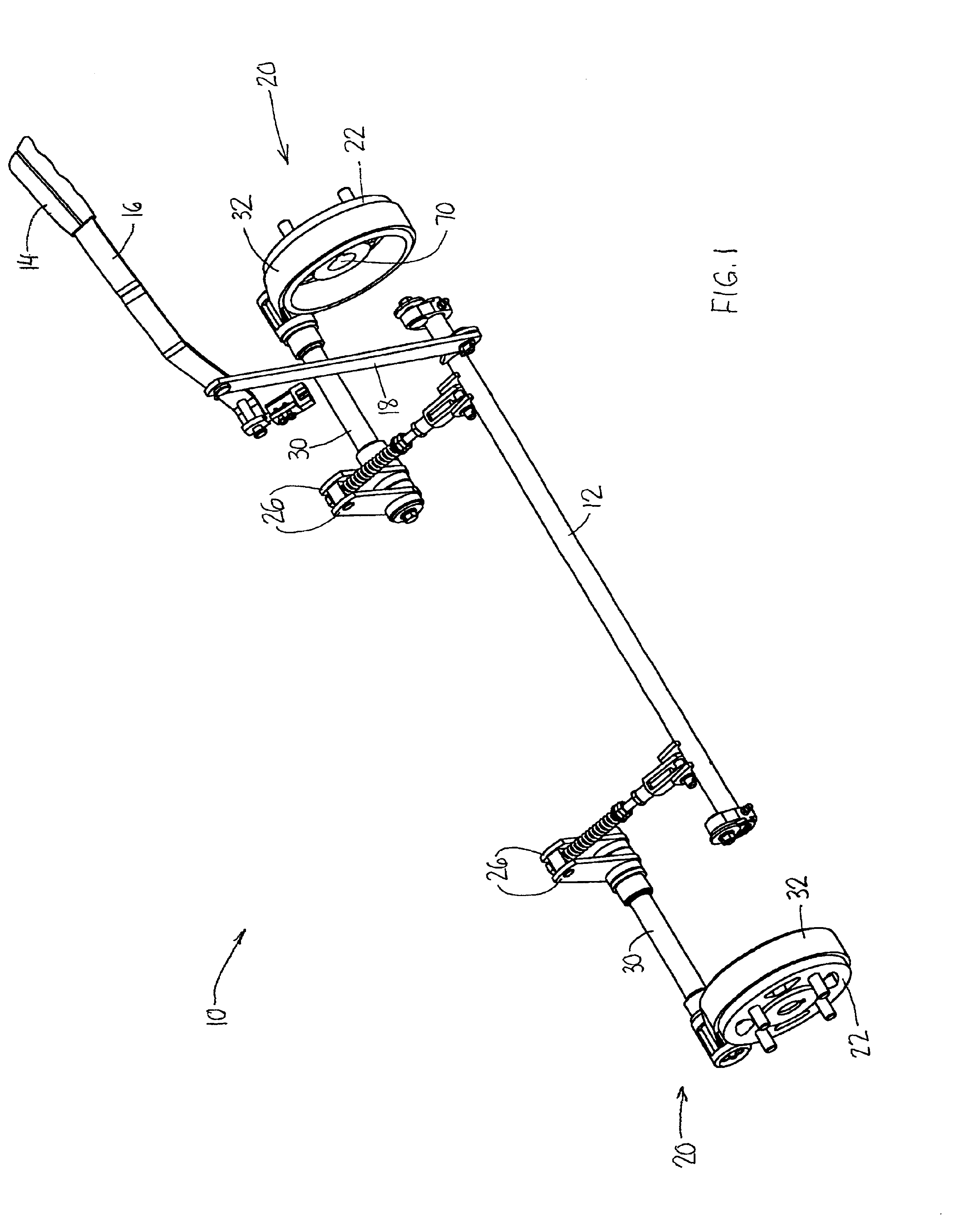
[0018]Looking to FIG. 1, there is shown the connection of a braking assembly 10 for use with a vehicle (not shown). The assembly 10 is shown connected on each of the left and right sides of the vehicle with a shaft 12 provided therebetween.

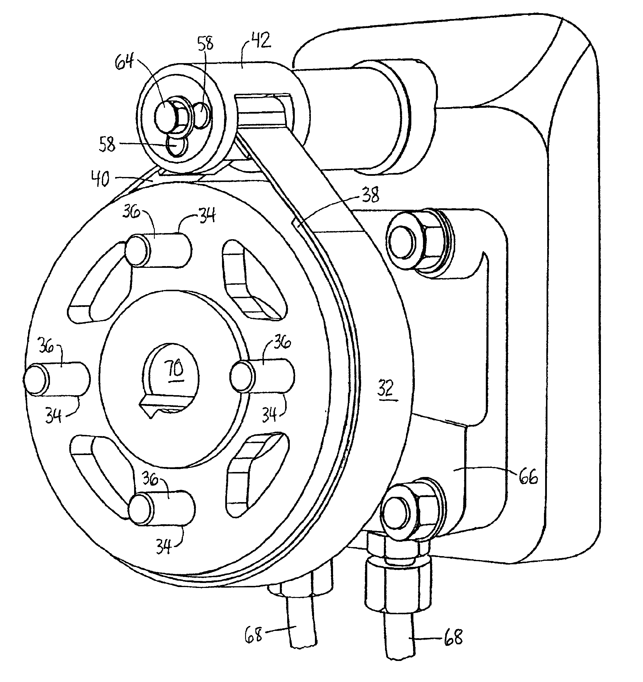
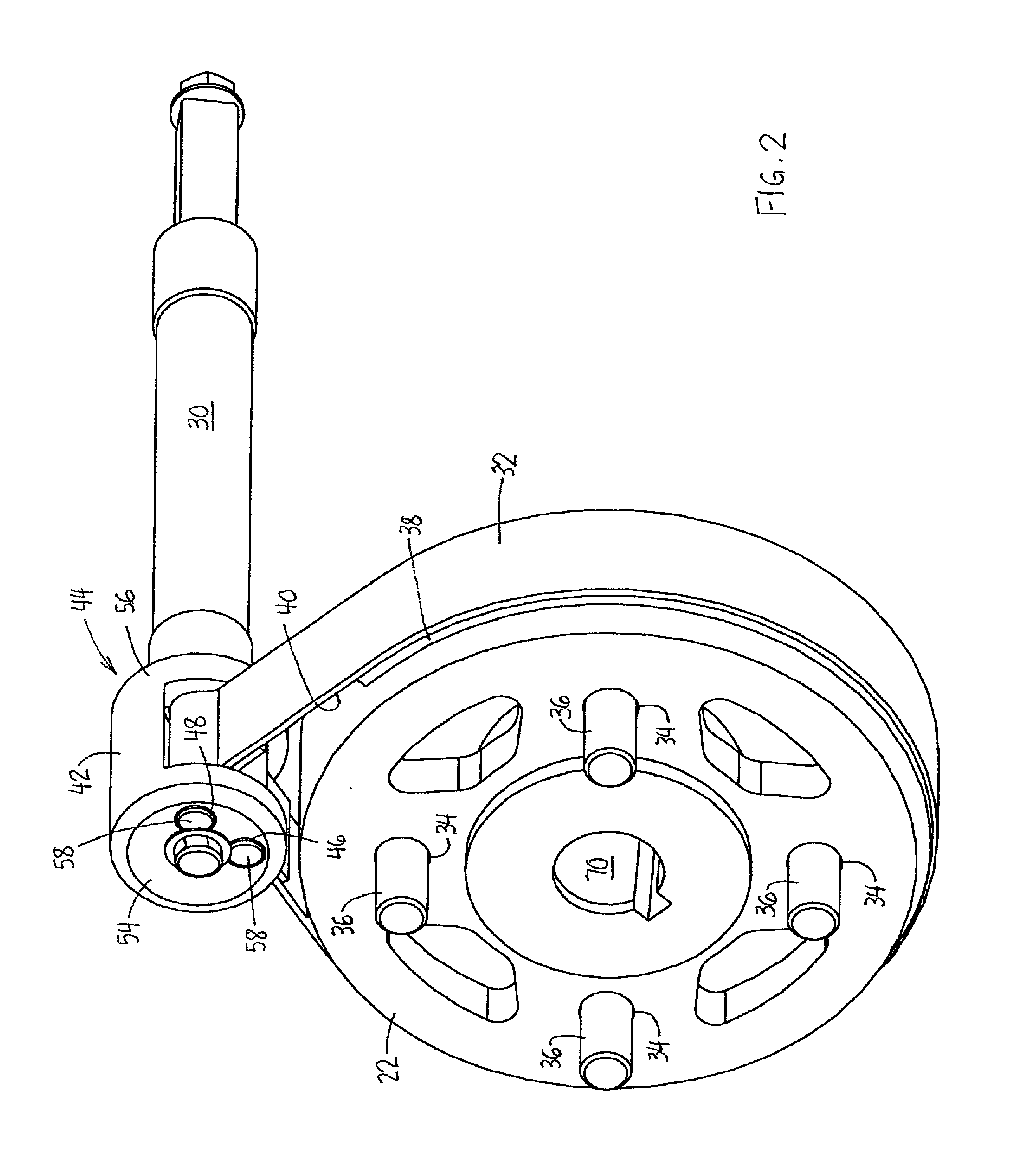
[0019]The braking assembly 10 consists of a brake lever 14 attached to and including an angular bar 16. The lever 14 is connected with a vertically extending linkage 18 for actuating a band assembly 20 to apply frictional force on the outer surface of a drum 22 and thereby retard motion of an attached wheel (not shown). While the preferred embodiment uses the band brake in conjunction with a vehicle wheel, it is to be understood that the band brake could be used with other rotating members. Connecting the band assembly 20 with the shaft 12 is a rod 24 attaching the shaft 12 to a pair of upstanding members 26 as is shown in FIG. 1. Disposed on the rod 24 is a spring 28 for biasing the lever 14 to a rearward position after the lever 14 has been move...


PUM


Abstract

A band brake for retarding the motion of an associated rotatable member. The brake acts to resist motion of the rotatable member through actuation of both of its ends by a cylindrical actuating member. The band is connected with and carried by actuator so as to allow the band to move with and respond in the same direction as the actuator. In doing so, greater opportunity exists for the structure connecting the band to the actuator to withstand and resist yielding upon application of force to the actuator.

Description

FIELD OF THE INVENTION[0001]This invention relates to a band brake that permits increased braking capacity and structural integrity while being small enough to fit within a confined space such as the wheel hub of a vehicle with which it is associated.BACKGROUND OF THE INVENTION[0002]It is commonly known that a band brake assembly has been used to retard the rotational force of a rotatable drum with which a ground engaging wheel of a vehicle is connected. The band brake applies a frictional force to the outer surface of the drum. When applied, this frictional force acts to slow rotation of the wheel by counteracting a torque or rotational force conveyed to the drum by the vehicle transmission. Upon sufficient application of this frictional force, the drum and the wheel with which it is associated will slow or cease to rotate.[0003]Band brakes, in general, have been used according to at least two designs for applications which include and extend beyond retarding motion of a wheel. Man...

Claims


Application Information

Patent Timeline
IPC IPC(8): F16D65/14F16D49/00F16D49/08
CPCF16D49/08F16D2121/14F16D2125/56
Inventor VAN WOUW, ROB
Owner DEERE & CO
Why Eureka
Try Eureka