Electromagnetic valve

Active Publication Date: 2005-08-04
ANDREAS STIHL AG & CO KG
View PDF4 Cites 17 Cited by
  • Summary
  • Abstract
  • Description
  • Claims
  • Application Information

AI Technical Summary

Benefits of technology

[0004] The flow channel opens at the peripheral region of the armature plate and hinders the electromagnetic flux only slightly. The coil and the iron core can be configured small while, at the same time, generating adequate forces on the armature plate. The armature plate is the only movable part so that only low forces are needed.
[0005] An advantageous configuration results when a second flow channel opens at the side of the armature plate facing away from the coil with this flow channel being provided for connecting to the first flow channel. The first flow channel is especially closed directly by the armature plate when there is current flow. Additional sealing elements thereby become unnecessary. A magnetically advantageous configuration results when the first and the second flow channels can be connected via an annular gap conf

Problems solved by technology

Additional sealing elements

Method used


Image

  • Electromagnetic valve
  • Electromagnetic valve
  • Electromagnetic valve

Examples


Example

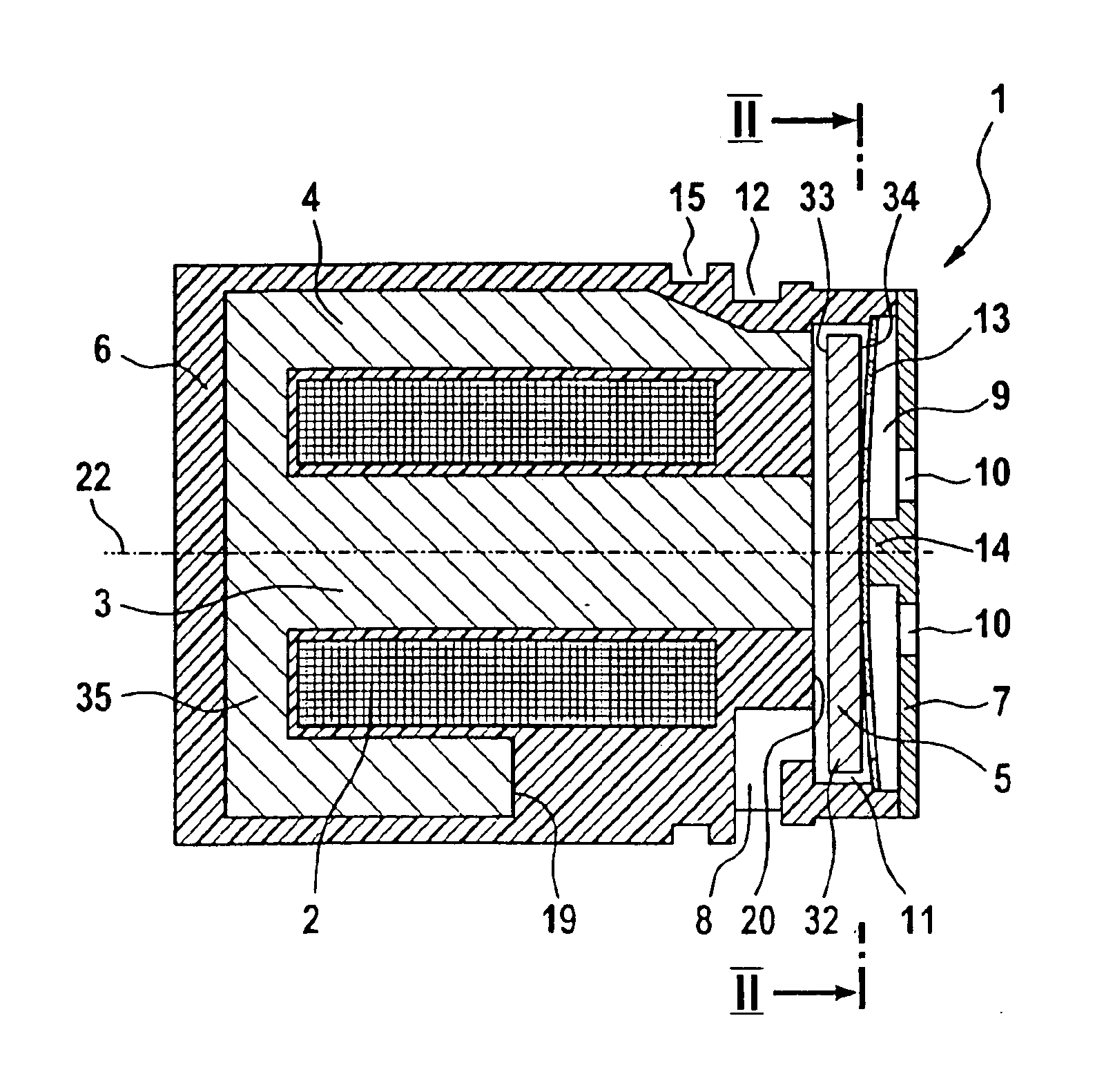
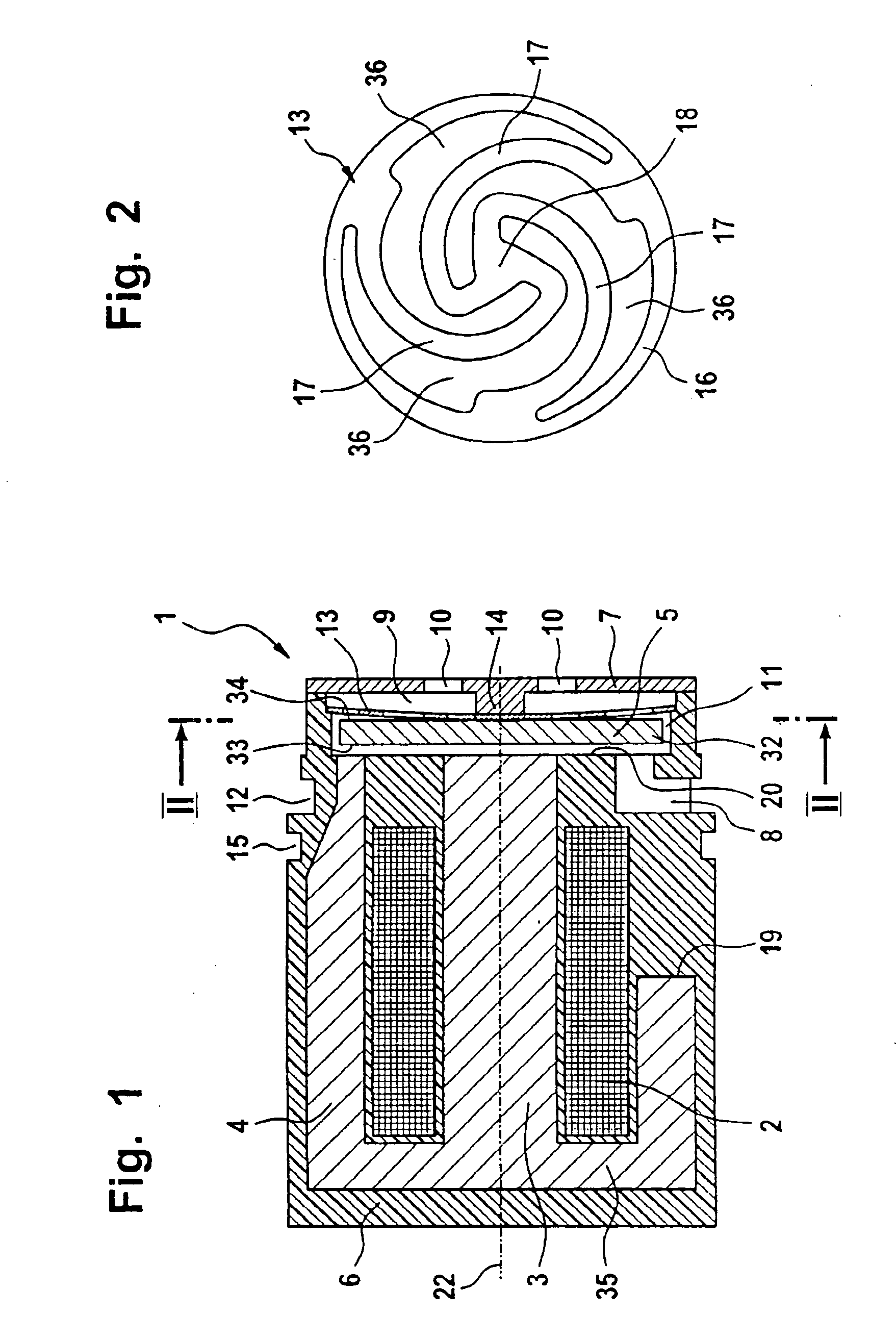
[0014] The electromagnetic valve 1 shown in FIG. 1 has a coil 2 in which an iron core 3 is arranged. The iron core is configured as one piece with a yoke 4 surrounding the coil 2 at its outer periphery. The coil 2 and the yoke 4 with the iron core 3 are arranged in a housing 6. The components are injection molded in the plastic which forms the housing 6. The yoke 4 is configured to have a pot-like shape and the base 35 of the yoke 4 is connected to the iron core 3. At the end of the yoke 4 facing away from the base 35, an armature plate 5 is movably journalled in the direction of the longitudinal axis 22 of the coil 2.

[0015] The housing 6 is closed by a housing cover 7 at the end facing away from the base 35 of the yoke 4. A center stop 14 is arranged on the housing cover 7 and limits the movement of the armature plate 5 in the direction of the longitudinal axis 22 of the coil.

[0016] The armature plate 5 is configured to have the shape of a circular disc and is journalled in the h...


PUM


Abstract

An electromagnetic valve (1, 21) includes a coil (2) which is fixedly connected to an iron core (3). An armature plate (5) is movably journalled in the direction of the coil longitudinal axis (22) relative to the iron core (3). At least two flow channels (8, 9; 26, 27, 28, 29) open at the armature plate (5) and are fluidly separated from each other when a current flows in the coil (2). A small structural size with a simple manufacture of the electromagnetic valve (1, 21) is achieved in that a flow channel (8; 26, 27, 28) opens in the peripheral region (32) of the armature plate (5) at the end (33) of the armature plate (5) facing toward the coil (2).

Description

BACKGROUND OF THE INVENTION [0001] German patent publication 201 04 770 discloses an electromagnetic valve having a coil in which an iron core is mounted. An armature plate is arranged on the iron core and carries a sealing nub. The iron core includes an axial bore which is closed by the sealing nub when there is a current flow in the coil. The axial bore in the iron core negatively influences the magnetic flux in the iron core. The force, which is available for pulling the armature plate, is thereby reduced. In order to be able to generate a sufficiently large force, a larger coil must be used. In this way, the entire structural size of the arrangement is increased. SUMMARY OF THE INVENTION [0002] It is an object of the invention to provide an electromagnetic valve of the kind described above which can be manufactured with few parts and has a small structural size. [0003] The electromagnetic valve of the invention includes: an iron core; a coil defining a longitudinal axis and bein...

Claims


Application Information

Patent Timeline
IPC IPC(8): F16K31/06
CPCF16K31/0655
Inventor NICKEL, HANSNAEGELE, CLAUS
Owner ANDREAS STIHL AG & CO KG
Why Eureka
Try Eureka