Hermetic compressor

a compressor and hermetic technology, applied in the direction of positive displacement liquid engines, pumps, machines/engines, etc., can solve the problems of oil lift force in the upper part of the oil feed path, the main oil feed path may not feed and the problem of hermetic compressors having the above-mentioned oil feed unit is problematic, so as to achieve efficient feeding of a sufficient amount of lubricating oil and improve the structure of the oil feed structur

Inactive Publication Date: 2005-06-02
SAMSUNG GWANGJU ELECTRONICS CO LTD
View PDF3 Cites 20 Cited by
  • Summary
  • Abstract
  • Description
  • Claims
  • Application Information

AI Technical Summary

Benefits of technology

[0009] Accordingly, it is an aspect of the present invention to provide a hermetic compressor, which has an improved oil feed structure to generate a sufficient force which lifts oil upward even when a rotating shaft rotates at a low speed, thus efficiently feeding a sufficient amount of lubricating oil to a plurality of drive parts.

Problems solved by technology

However, the conventional hermetic compressor having the above-mentioned oil feed unit is problematic as follows.
In the above state, the main oil feed path may fail to feed a sufficient amount of lubricating oil to the spiral oil feed groove.
Furthermore, the upper oil feed path linearly extends upward in the eccentric part of the rotating shaft while being in parallel to the central axis of the rotating shaft, the oil lift force in the upper oil feed path may be reduced, so that the conventional oil feed unit of the hermetic compressor may fail to feed a sufficient amount of lubricating oil to the piston of the compression unit.

Method used


Image

  • Hermetic compressor
  • Hermetic compressor
  • Hermetic compressor

Examples


Embodiment Construction

[0027] Reference will now be made in detail to the present preferred embodiments of the present invention, examples of which are illustrated in the accompanying drawings, wherein like reference numerals refer to like elements throughout. The embodiments are described below in order to explain the present invention by referring to the figures.

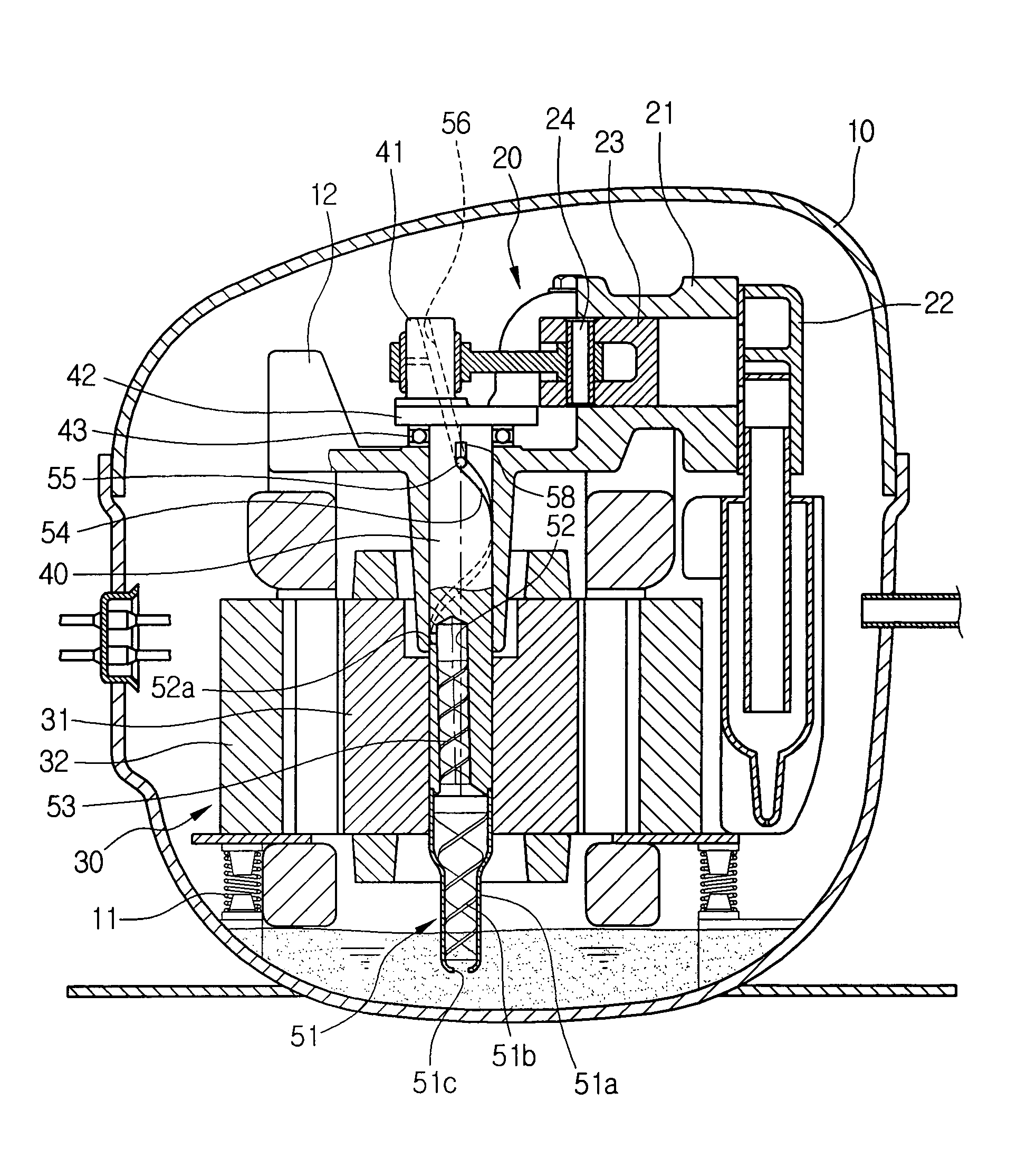
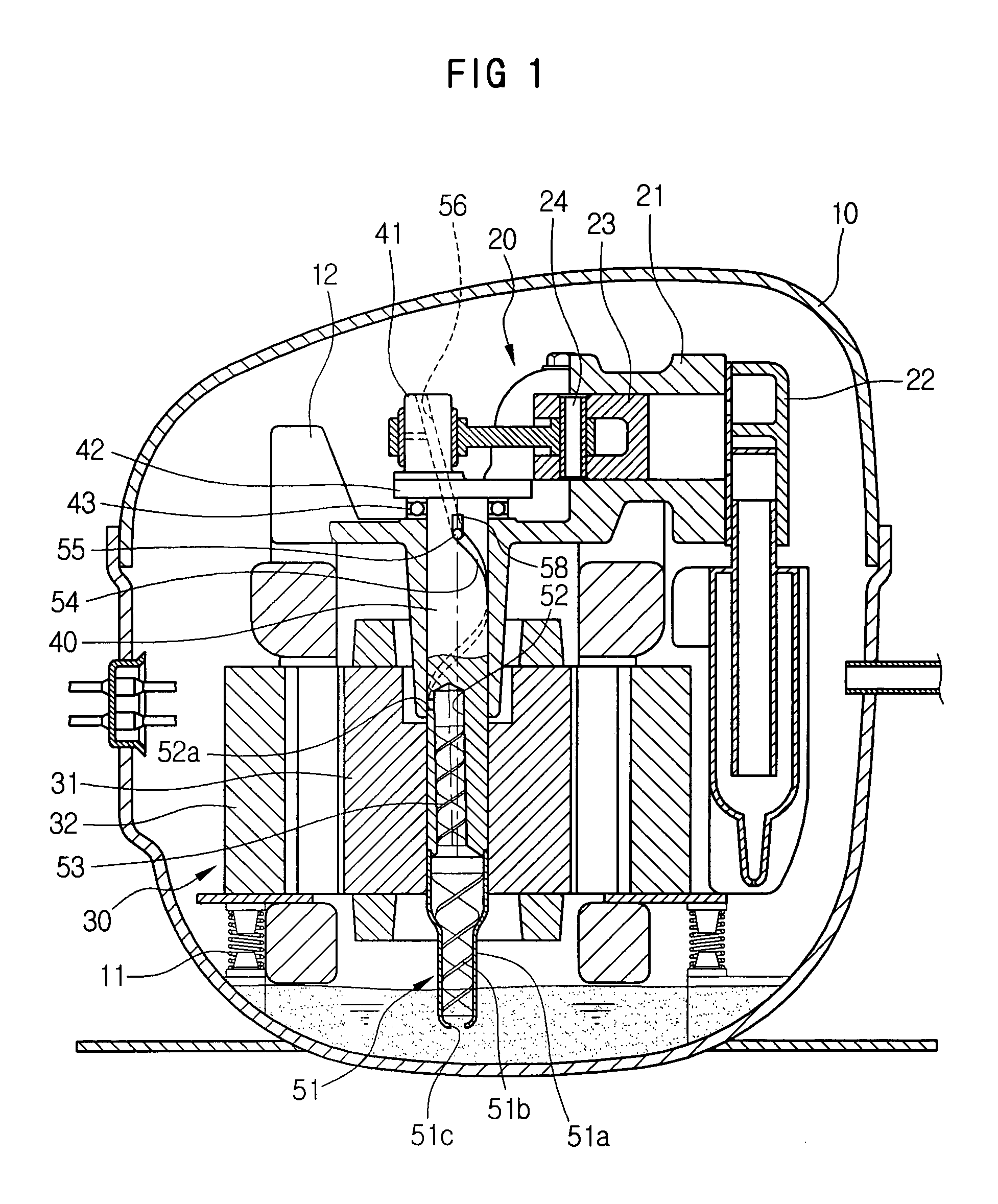
[0028] As shown in FIG. 1, the hermetic compressor according to the embodiment of the present invention has a hermetic casing 10, a frame 12 installed in the hermetic casing 10 while being supported by a plurality of damping units 11, a compression unit 20 provided on an upper portion of the frame 12, and a drive unit 30 provided in a lower portion of the frame 12 to drive the compression unit 20.

[0029] The hermetic compressor further includes a rotating shaft 40 which is vertically installed in the frame 12 while being supported by a shaft support part 13 of the frame 12 to rotate relative to the frame 12. The rotating shaft 40 transmits a ro...


PUM


Abstract

A hermetic compressor provided with an improved oil feed structure to efficiently feed lubricating oil to a plurality of drive parts. The hermetic compressor includes a hermetic casing, a frame provided in the hermetic casing, a drive unit provided in a lower portion of the frame, a compression unit provided on an upper portion of the frame, a rotating shaft vertically installed in the frame to transmit a rotating force of the drive unit to the compression unit, with an eccentric part provided on an upper end of the rotating shaft and coupled to the compression unit, and an oil feed unit provided on the rotating shaft to feed oil from a bottom of the hermetic casing to the plurality of drive parts. The oil feed unit includes a first oil pickup unit provided on a lower end of the rotating shaft to lift the oil upward from the bottom of the hermetic casing, a first oil feed path provided in the rotating shaft above the first oil pickup unit while being eccentric from a central axis of the rotating shaft, a spiral oil feed groove provided around the rotating shaft above the first oil feed path and communicating with the first oil feed path, a second oil feed path provided in the eccentric part and communicating with the spiral oil feed groove, and a second oil pickup unit provided in the first oil feed path to increase an oil lift force.

Description

CROSS-REFERENCE TO RELATED APPLICATION [0001] This application claims the benefit of Korean Patent Application No. 2003-85710, filed Nov. 28, 2003 in the Korean Intellectual Property Office, the disclosure of which is incorporated herein by reference. BACKGROUND OF THE INVENTION [0002] 1. Field of the Invention [0003] The present invention relates, in general, to hermetic compressors and, more particularly, to a hermetic compressor which has an improved oil feed structure to efficiently feed lubricating oil using a rotating force of a rotating shaft to a plurality of drive parts. [0004] 2. Description of the Related Art [0005] As an example of conventional techniques of hermetic compressors, Japanese Patent Laid-open Publication No. 2000-205130 discloses a hermetic compressor having an oil feed unit to feed lubricating oil using a rotating force of a rotating shaft to a plurality of drive parts. The oil feed unit of the above-mentioned hermetic compressor has an oil piece, a main oi...

Claims


Application Information

Patent Timeline
Patent Type & Authority Applications(United States)
IPC IPC(8): F01M1/00F04B39/02F04B35/00F04B39/00F16N7/36
CPCF16N7/366F04B39/023F04B39/02
Inventor SHIN, KYU SHIK
Owner SAMSUNG GWANGJU ELECTRONICS CO LTD
Why Eureka
Try Eureka