

Mirror Angle Adjusting Device
a technology of mirror angle and adjustment device, which is applied in the direction of mountings, instruments, vehicle components, etc., can solve the problems of variable contact pressure and use of lubricant, and achieve the effect of stabilizing the holding of the pivot pla
- Summary
- Abstract
- Description
- Claims
- Application Information
AI Technical Summary
Benefits of technology
Problems solved by technology
Method used
Image

Examples
Embodiment Construction
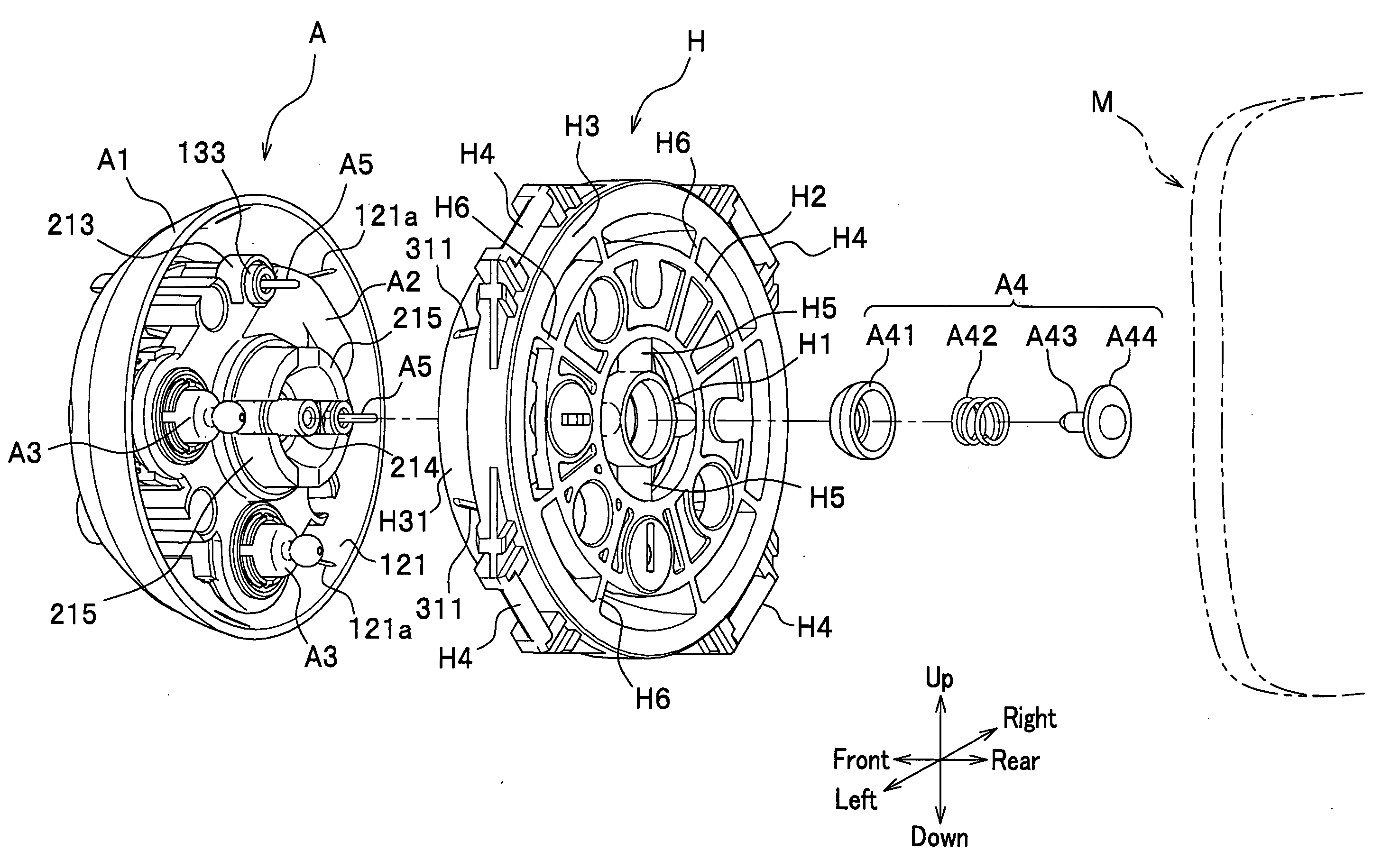
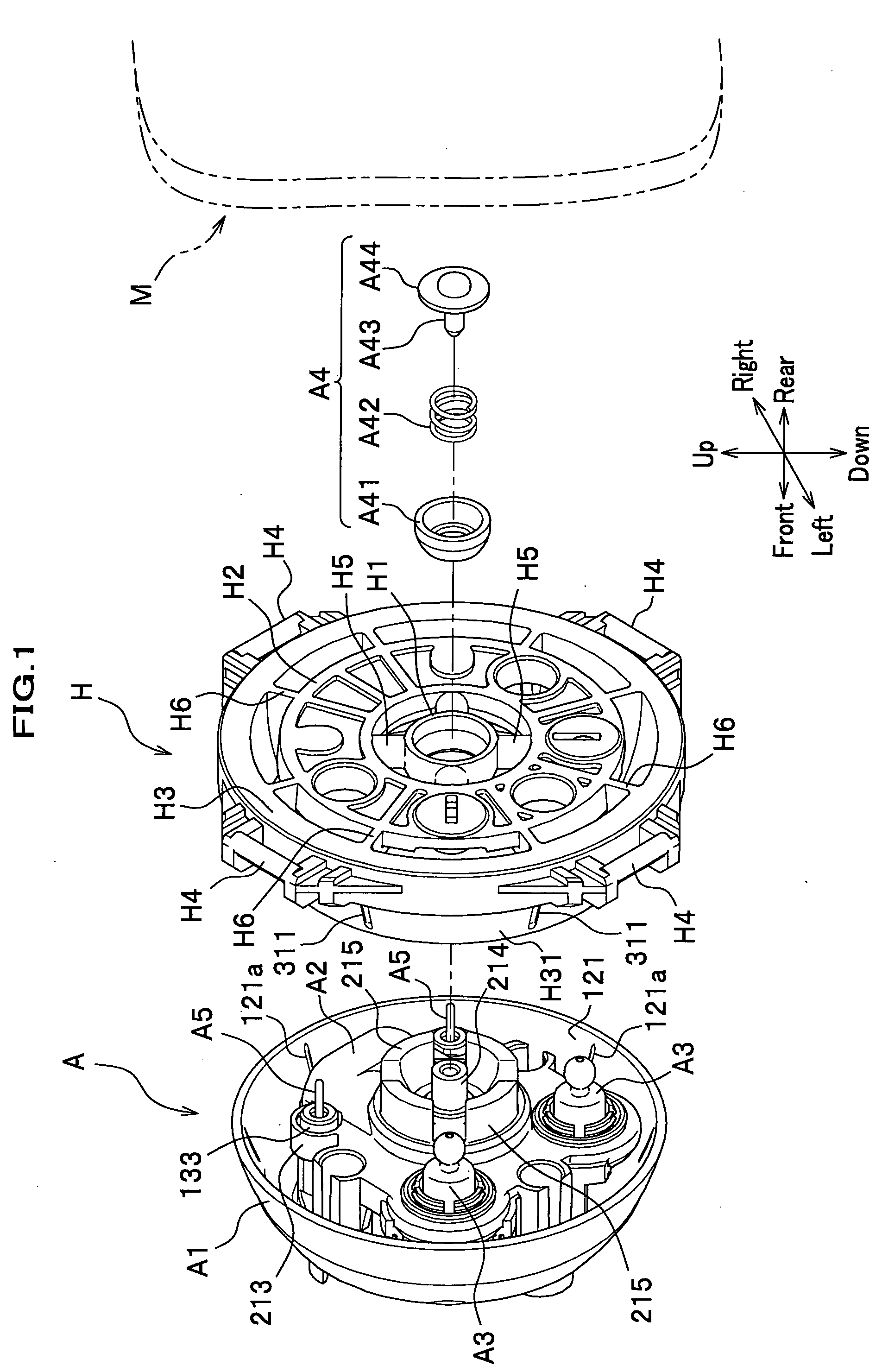
[0041]The best modes for carrying out the present invention are described in detail with reference to the drawings. In the following embodiment, an example is described assuming that a mirror angle adjusting device is built in a rear-view outer mirror provided on a lateral side of an automobile. The terms “front and rear”, “right and left” and “up and down” used in this specification are based on the state where the outer mirror is provided on a lateral side of an automobile.
[0042]The mirror angle adjusting device according to the embodiment of the present invention includes, as shown in FIG. 1, a pivot plate H attached to a back side (in this embodiment, on a front side) of a mirror M for holding the mirror M via a mirror holder not shown; and an actuator A for holding the pivot plate H. It is to be noted that the actuator A is fixed to a mirror housing MH, or a support frame SF (see FIG. 13) integrally mounted on the support frame SF.
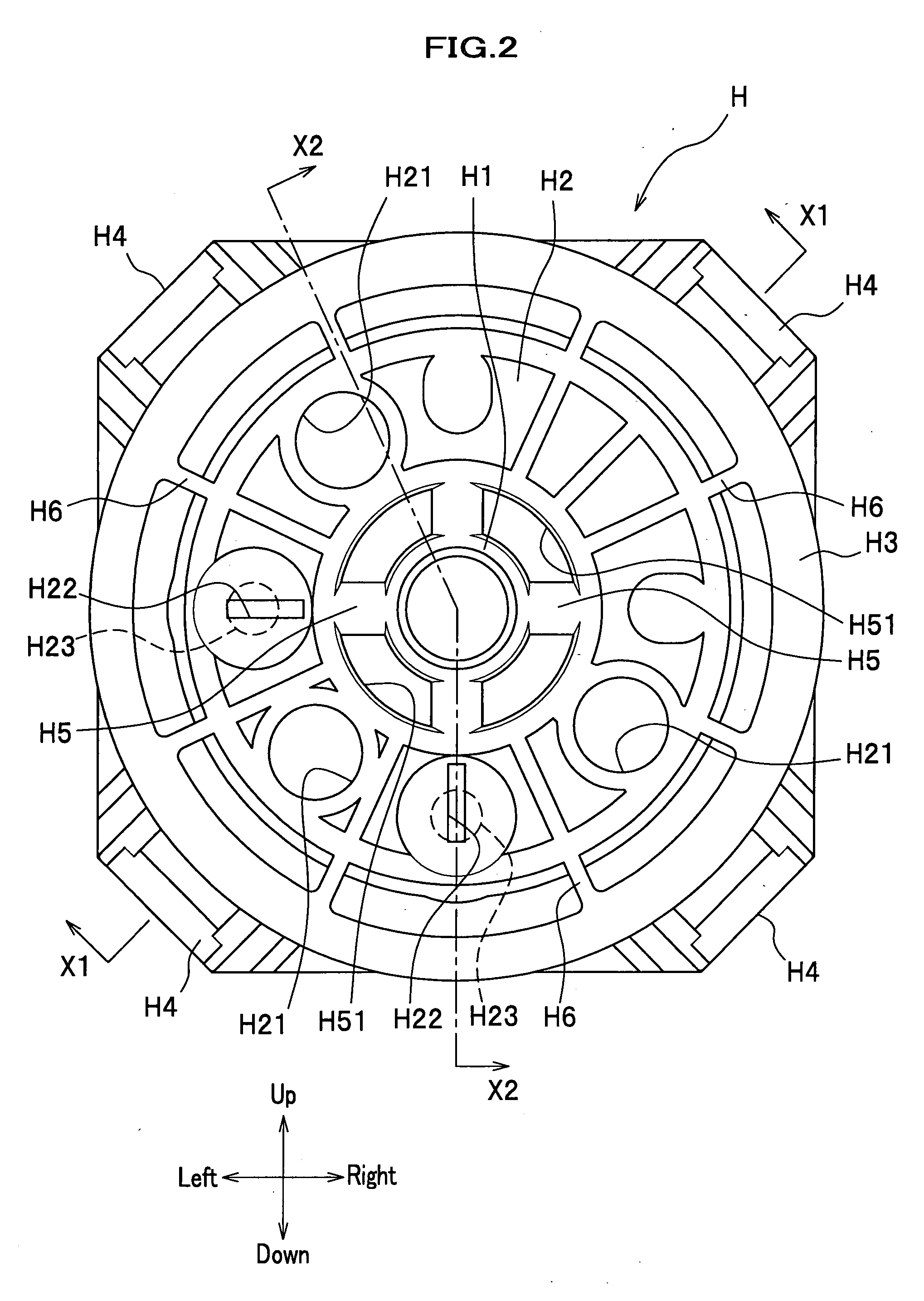
(Pivot Plate)
[0043]The pivot plate H includes a...
PUM
 Abstract
Description
Claims
Application Information