Rail Threading Mechanism

a threading mechanism and rail technology, applied in the direction of railway track construction, railway tracks, construction, etc., can solve the problems of difficulty in unloading rails, difficult, time-consuming and laborious jobs, and conventional practice problems, and achieve effective and reliable unloading of rails, and the effect of reducing the width of the machin

Active Publication Date: 2009-04-16
HERZOG CONTRACTING
View PDF1 Cites 15 Cited by
  • Summary
  • Abstract
  • Description
  • Claims
  • Application Information

AI Technical Summary

Benefits of technology

[0011]The invention is characterized in another respect by the provision of threading mechanisms which unload the rails and which may be extended sidewardly for operation to unload rails on a rail bed and also may be retracted for storage in a narrow profile position to minimize the width of the machine for transport along a roadway without exceeding highway width regulations. In addition to swinging in and out, another aspect of the invention is that the threading mechanisms may be pivoted up and down for more secure storage in the transport position.
[0012]Another aspect that characterizes the invention is a thread box construction in which opposing jaws are provided to accommodate easy receipt of the rails when the jaws are open, and to assure secure and accurate positioning of the rails within the thread box roller system to allow effective and reliable unloading of the rails when the jaws are closed. This construction has the advantage of not requiring precise application of the rails to the thread boxes as is required in the case of closed thread boxes.
[0013]The invention is characterized by the additional feature of a rail clamp that is uniquely constructed to accommodate effective application of the rails to the threading mechanisms. In this regard, the rail clamp is equipped with one and preferably two dog elements that can be clamped rigidly to the rails to enable the clamp to effectively feed the rails to the threading mechanisms. It is preferred for two dogs to be included, pivoting in opposite directions to clamp against the rail, because this has the advantage of enabling the rails to be manipulated back and forth without slippage, as is sometimes necessary when the rails are being applied to the thread boxes.
[0014]Still another aspect of the invention involves the provision of a rail saw that is characterized by a variety of novel features each representing an improvement independently of the others. Among the features exhibited by the saw are a secure clamping system for holding the rail in place relative to the saw blade; a leveling system for assuring a cut precisely perpendicular to the rail axis; assurance that a cut is initiated only when the saw blade has reached the design rotational speed; automatic reduction in the rate of feeding of the blade through the rail if the blade rotational speed is too slow, or if the back pressure of the hydraulic blade rotation motor is too high, or if the electric motor used to feed the blade draws current at an excessive level; and automatic initiation of a back feeding stroke of the saw through the cut after the cut has been completed, with the saw blade continuing to rotate during the back feeding stroke and the blade feed and rotation motors being deactivated automatically when the end of the back feeding stroke is reached.
[0015]From an overall standpoint, the invention is characterized by all of the foregoing advantages and benefits, as well as added advantages and benefits including reduction in labor requirements, enhanced safety due to the automated nature of the operations allowing personnel to remain remote from the site of potentially dangerous operations, and more efficient and reliable rail unloading, all accomplished at less cost and more expediently than has been possible in the past.

Problems solved by technology

The laying of railway track, either in the initial construction of a railway line or when replacing existing rails, is necessarily a difficult, time consuming and labor intensive job.
The rails are unloaded form the special car using this complicated equipment in a time consuming process that involves repeated starts and stops of the locomotive that pulls the special rail unloading car along the track, and manual handling of the rails and equipment.
This conventional practice is problematic in several respects.
It requires significant manual labor to handle the equipment and connect it with the rails, and workers are subjected to the risk of serious injury because they must physically be present at the site of the operations that are carried out.
The time required to unload the rails in this manner adds significantly to both the labor costs and to the overall maintenance costs of the railway.
Although equipment has been proposed to attempt to automate the process more fully and reduce the need for extensive manual labor and the risk of personal injury, such equipment has not been wholly satisfactory.
Aside from the cost and maintenance problems resulting from the need for such complicated machinery, the Theurer equipment operates only on railway track.
Consequently, when the rails need to be transported over lengthy distances, they are restricted to rail transportation and cannot be transported over-the-road along highways or other roadways that may be a more efficient mode of transportation.
Accordingly, there is a need to couple and uncouple the rail unloading equipment from the different towing vehicles required for the different modes of travel, and this adds to the time, cost and complexity of the entire operation.
To accomplish this, the thread boxes must be spaced apart far enough to enable the rails to be unloaded outwardly of the rails and the ends of the ties that are installed on the rail bed, and this can result in equipment that is too wide to travel safely on many roadways.

Method used


Image

  • Rail Threading Mechanism
  • Rail Threading Mechanism
  • Rail Threading Mechanism

Examples


Embodiment Construction

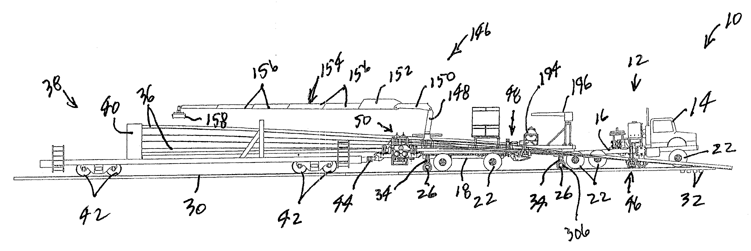
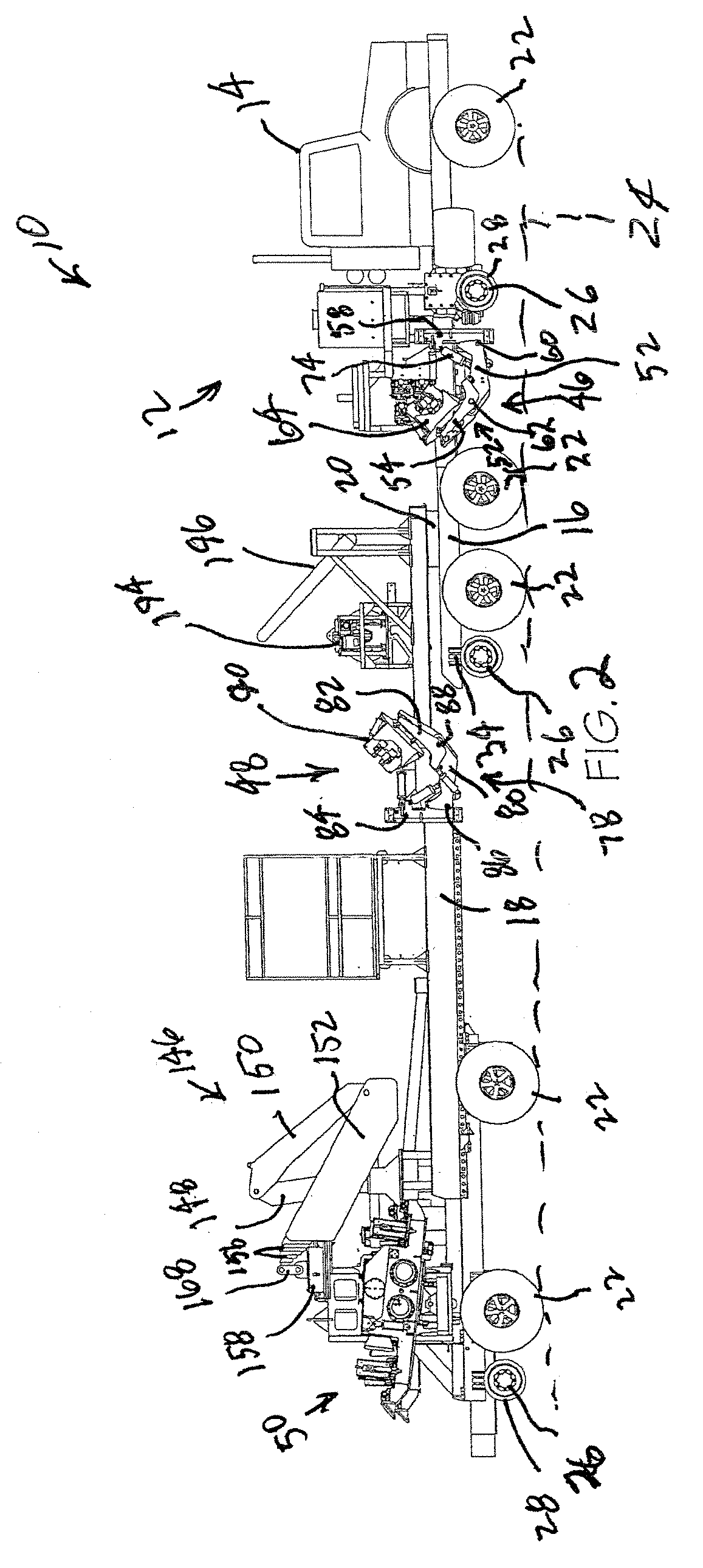
[0034]Referring now to the drawings in more detail and initially to FIGS. 1 and 2, numeral 10 generally designates a rail unloading machine constructed in accordance with a preferred embodiment of the present invention. The machine 10 includes a self-propelled vehicle 12 having an operator's cab 14 mounted on a rigid frame 16. The vehicle 12 is equipped with a conventional engine for propelling the vehicle, such as a gasoline or diesel engine. The vehicle 12 may be generally in the nature of a conventional tractor such as that commonly included in over the road tractor-trailers. A rear frame 18 is coupled to frame 16 by means of a conventional swivel coupling 20 (FIG. 2).

[0035]The frames 16 and 18 are each equipped with a plurality of conventional wheels and tires 22 of the type used on tractor-trailers for over-the-road travel along a roadway such as the roadway 24 shown in FIG. 2. Each frame 16 and 18 is also equipped with a plurality of flanged rail wheels 26 having flanges 28 on...


PUM

PropertyMeasurementUnit
lengthsaaaaaaaaaa
rotationaaaaaaaaaa
timeaaaaaaaaaa

Abstract

A rail threading mechanism for a rail handling vehicle includes a thread box mounted on the outer end of a manipulating arm. The thread box includes a platform and a pair of jaws pivotally connected to the platform and moveable between open and closed positions. The platform includes a support roller for rollingly engaging the flat bottom of a rail. Each jaw include a plurality of jaw rollers positioned for rollingly engaging a rail positioned on the support roller when the respective jaw is in the closed position. The jaw rollers on each jaw preferably include a pair of base rollers positioned for engaging an edge of the base of the rail, a pair of flange top rollers positioned for engaging a top surface of the top flange of the rail, and a flange side roller positioned for engaging an edge surface of the top flange of the rail.

Description

CROSS-REFERENCE TO RELATED APPLICATIONS[0001]This application is a division of application Ser. No. 11 / 613,043 filed Dec. 19, 2006.FIELD OF THE INVENTION[0002]This invention relates in general to railway maintenance equipment and deals more particularly with rail unloading apparatus used to unload lengthy ribbon rails along railway lines.BACKGROUND OF THE INVENTION[0003]The laying of railway track, either in the initial construction of a railway line or when replacing existing rails, is necessarily a difficult, time consuming and labor intensive job. Standard industry practice involves constructing individual rail sections and the welding them together end to end to form lengthy ribbon rails that may be as long as 1800 feet or more.[0004]The ribbon rails have traditionally been transported to their installation site by transporting them along the railway and loading them onto special rail cars equipped with bunks that receive the rails on several different tiers. The rails are unloa...

Claims


Application Information

Patent Timeline
Patent Type & Authority Applications(United States)
IPC IPC(8): E01B29/16
CPCE01B29/16Y10T83/7697E01B31/04
Inventor BOUNDS, IVAN E.
Owner HERZOG CONTRACTING
Why Eureka
Try Eureka