Methods for stabilizing bone using spinal fixation devices

a technology of spinal fixation and bone, which is applied in the field of spinal fixation devices, can solve the problems of reducing nerve function, affecting the treatment effect and affecting the recovery of patients,

Inactive Publication Date: 2008-06-05
STRYKER EURO OPERATIONS HLDG LLC
View PDF32 Cites 32 Cited by
  • Summary
  • Abstract
  • Description
  • Claims
  • Application Information

AI Technical Summary

Benefits of technology

[0016]In certain preferred embodiments, the seat is shaped to allow the coupling element to pivot with respect to the anchoring element. Before the coupling element is locked into place with respect to the anchoring element, the coupling element is pivotable and rotatable for capturing a spine rod in the rod receiving openings thereof. The combination of the pivotable coupling element and the tilted arrangement of the first and second portions of the coupling element enable the coupling element to move over a broader range of angles for capturing a spine rod.
[0020]The coupling element preferably has an exterior surface, an upper end and a lower end, and rod-receiving openings that are open on the upper end and extend toward the lower end. The coupling element preferably has cuts formed between the exterior surface and the rod-receiving openings for minimizing the width of the coupling element. As a result, adjacent coupling elements may be more closely packed adjacent one another, because the cuts result in the coupling elements having less width.
[0024]The head of the anchoring element preferably has one or more depressions formed therein adapted for receiving a driver for driving the anchoring element into bone. The anchoring element preferably includes a reduced diameter neck for facilitating pivotal movement of the coupling element with respect to the anchoring element.
[0033]In another preferred embodiment of the present invention, a method of stabilizing bone includes providing a coupling element having first and second sections that are angled relative to one another, the coupling element having rod receiving openings for receiving an elongated member, assembling the coupling element with an anchoring element, and after the assembling step, securing the anchoring element in bone. The method includes moving the coupling element relative to the anchoring element to align the rod receiving openings with the elongated member, securing the orthopedic rod in the rod receiving openings, and after the securing step, locking the coupling element from further movement relative to the anchoring element.

Problems solved by technology

Patients that suffer from such conditions usually experience extreme and debilitating pain, as well as diminished nerve function.
There are many disadvantages associated with current spinal fixation devices. FIG. 1 show a prior art bone fixation device that is incapable of capturing spine rods when the rod capturing assemblies must be rotated to extreme angles.
Surgeons have encountered considerable difficulty when attempting to insert spinal fixation devices such as those disclosed in the above-mentioned '388 patent.
This is because the U-shaped heads atop adjacent screws are often out of alignment with one another due to curvature of the spinal column and the different orientation of adjacent pedicles receiving the screws.
This “bending the spine rod” solution serves to weaken the strength of the assembly and results in significantly longer operations, which increases the likelihood of surgical complications.

Method used


Image

  • Methods for stabilizing bone using spinal fixation devices
  • Methods for stabilizing bone using spinal fixation devices
  • Methods for stabilizing bone using spinal fixation devices

Examples


Embodiment Construction

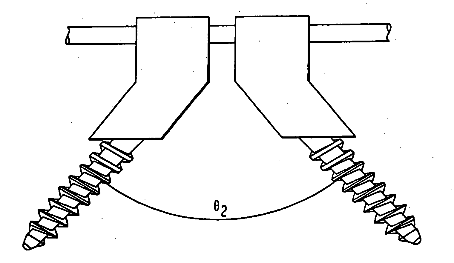
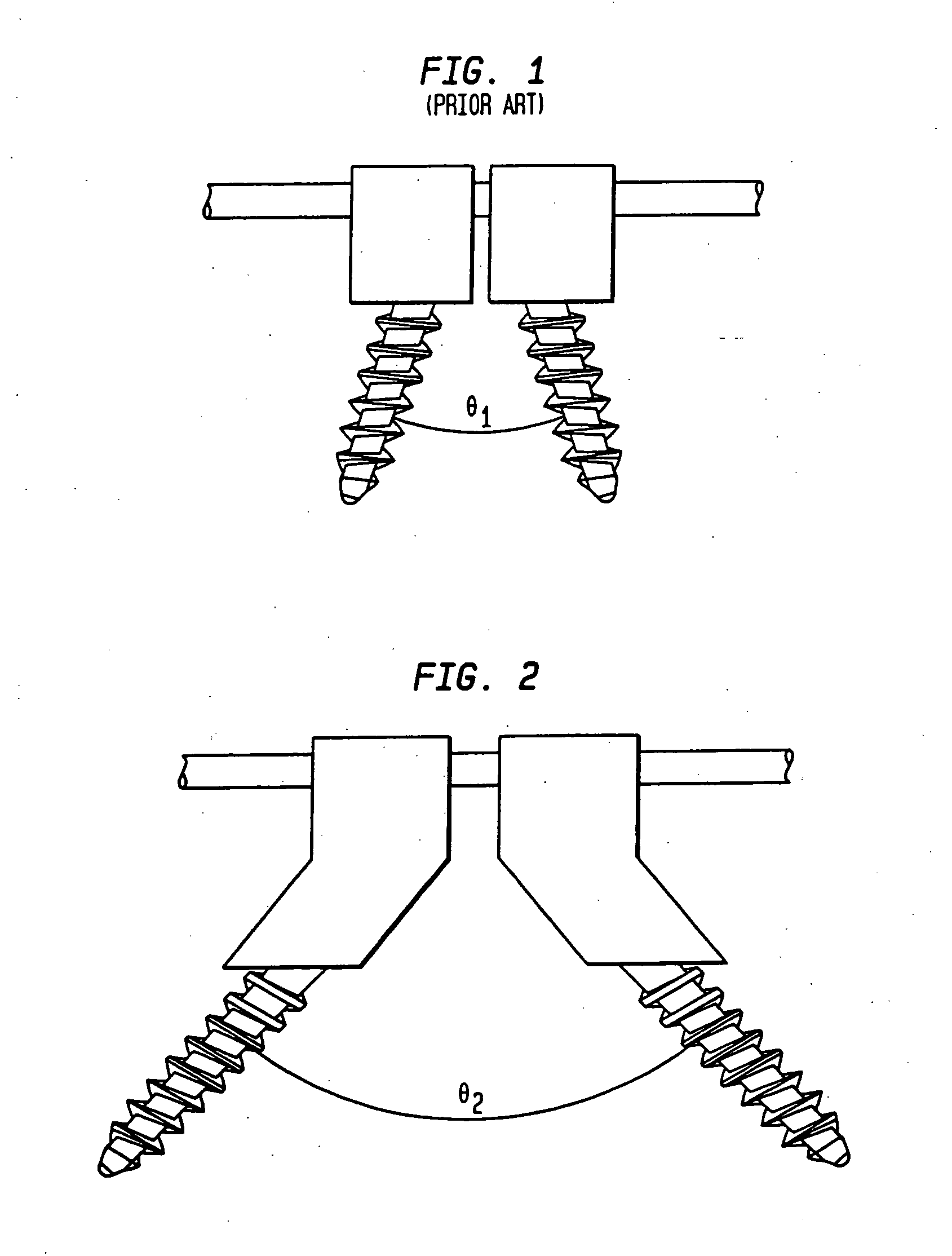
[0082]Referring to FIG. 2, the present invention is generally related to providing bi-axial coupling elements that are capable of pivoting over a broader range of angles (e.g. to an angle θ2 of up to about 110°), thereby providing for greater angulation than is possible with the prior art devices shown in FIG. 1.

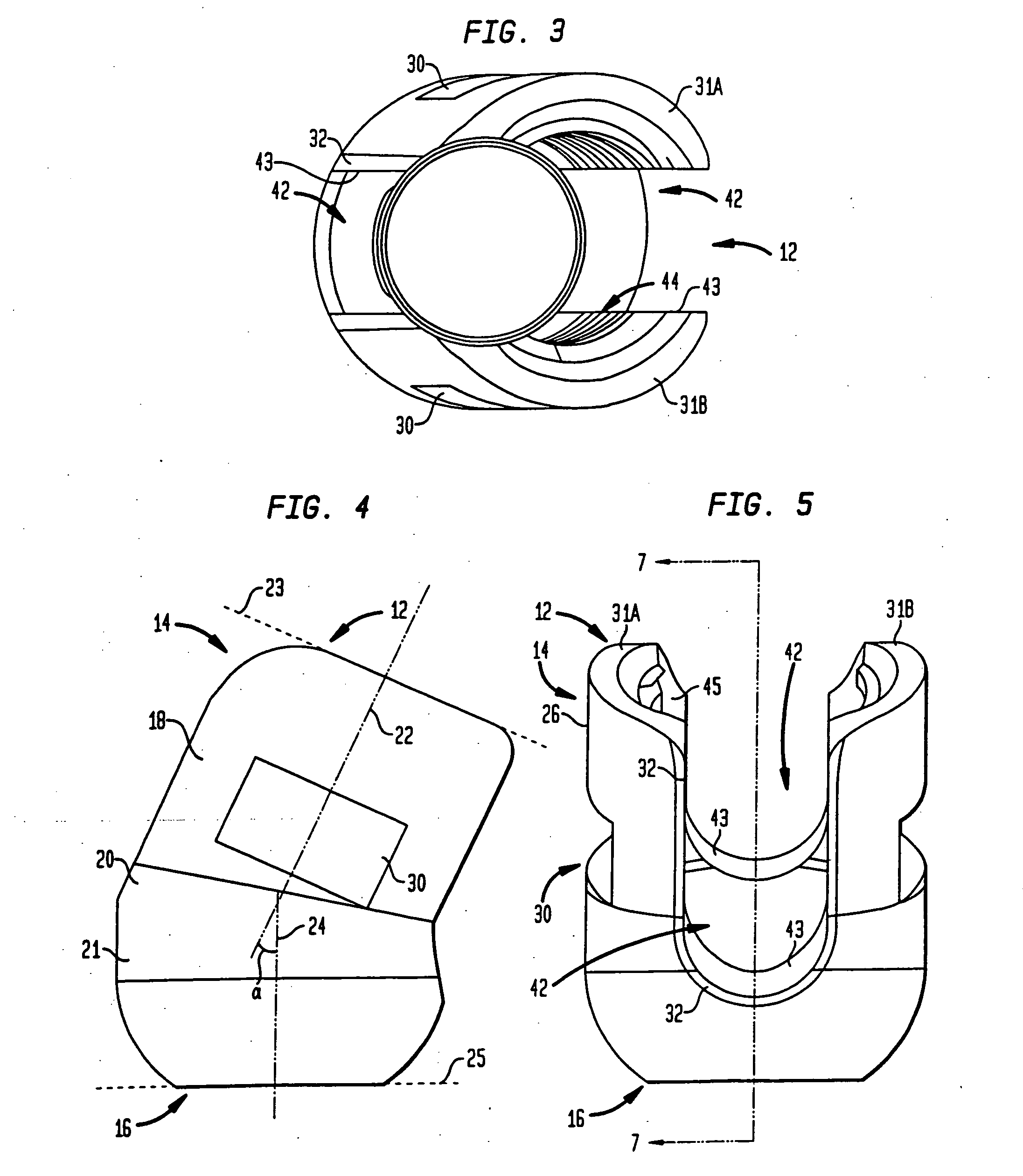
[0083]FIGS. 3-16 show a bone fixation assembly, in accordance with certain preferred embodiments of the present invention. The bone fixation assembly may be secured to the pedicles of vertebral bodies of a spinal column. Referring to FIGS. 3-7, the fixation assembly includes a coupling element 12 preferably made of a biologically inert material, preferably any metal customarily used for surgical devices and particularly those used for bone screws and pins, such as titanium or stainless steel. Other suitable materials for the coupling element include alloys, composite materials, ceramics or carbon fiber materials. Coupling element 12 has an upper end 14 and a lower end 16. Th...


PUM


Abstract

A method of stabilizing bone, such as a spine, includes providing a coupling element having first and second sections that are angled relative to one another, the coupling element having rod receiving openings for securing an elongated member such as an orthopedic rod, and assembling the coupling element with an anchoring element. The method includes securing the anchoring element in bone, moving the coupling element relative to the anchoring element to align the rod receiving openings with the orthopedic rod, securing the orthopedic rod in the rod receiving openings, and after the securing step, locking the coupling element from further movement relative to the anchoring element.

Description

CROSS-REFERENCE TO RELATED APPLICATIONS[0001]The present application is a continuation of U.S. patent application Ser. No. 10 / 832,214 filed Apr. 26, 2004, which is a divisional of U.S. patent application Ser. No. 10 / 091,068 filed Mar. 5, 2002, which claims the benefit of the filing date of U.S. Provisional Application No. 60 / 322,042, filed Sep. 14, 2001, the disclosures of which are hereby incorporated by reference herein.FIELD OF THE INVENTION[0002]The present invention relates generally to spinal fixation devices and more specifically relates to pedicle fixation assemblies.BACKGROUND OF THE INVENTION[0003]The spinal column is a highly complex system of bones and connective tissues that provides support for the body and protects the delicate spinal cord and nerves. The spinal column includes a series of vertebral bodies stacked one atop the other, each vertebral body including an inner or central portion of relatively weak cancellous bone and an outer portion of relatively strong c...

Claims


Application Information

Patent Timeline
Patent Type & Authority Applications(United States)
IPC IPC(8): A61B17/58A61B17/56A61B17/70A61B17/86A61B17/88
CPCA61B17/7032A61B17/7034A61B17/7037A61B17/7038A61B17/7035A61B17/861A61B17/7082A61B17/88A61B17/7041
Inventor CARBONE, JOHNMARKWORTH, AARONHORAN, MICHAELCROZET, YVES
Owner STRYKER EURO OPERATIONS HLDG LLC
Why Eureka
Try Eureka