Stator for Rotating Machine and Rotating Machine Using the Same

a technology of rotating machines and stators, which is applied in the direction of dynamo-electric machines, electrical apparatus, commutators, etc., can solve the problems of stator growth, increased width of coil ends, and increased stator size, so as to reduce the width in the axial direction of coil ends, reduce the width of radial direction of stators, and increase the creepage distance

Inactive Publication Date: 2009-06-04
HITACHI LTD
View PDF4 Cites 30 Cited by
  • Summary
  • Abstract
  • Description
  • Claims
  • Application Information

AI Technical Summary

Benefits of technology

[0015]With this construction, a plurality of conductors that connect stator windings in a multi-phase connection fashion are each substantially circular in cross-section, so that the width in the radial direction of the stator can be minimized. Moreover, since a plurality of conductors is arranged on the same plane, the width in the axial direction of the coil ends can be reduced. Therefore, the stator and the rotating machine can be miniaturized. By inserting between the conductor and the stator winding a connection plate provided with walls for increasing creepage distance between the adjacent conductors, insulation properties can be increased. On this occasion, winding the stator windings around divided cores makes assembling easier.
[0016]According to the present invention, a stator with a reduced size and a rotating machine with a reduced size can be provided.

Problems solved by technology

This raises a problem that the stator grows in size.
The technology disclosed in Japanese Laid-open Patent Publication No. 2006-246594 has a problem that the width of the coil end increases since the bus bars are stacked, so that the stator grows in size.
Therefore, the connection plate is not suited for rotating machines for high voltage operations although it is suitable for rotating machines for low voltage operations.

Method used


Image

  • Stator for Rotating Machine and Rotating Machine Using the Same
  • Stator for Rotating Machine and Rotating Machine Using the Same
  • Stator for Rotating Machine and Rotating Machine Using the Same

Examples


first embodiment

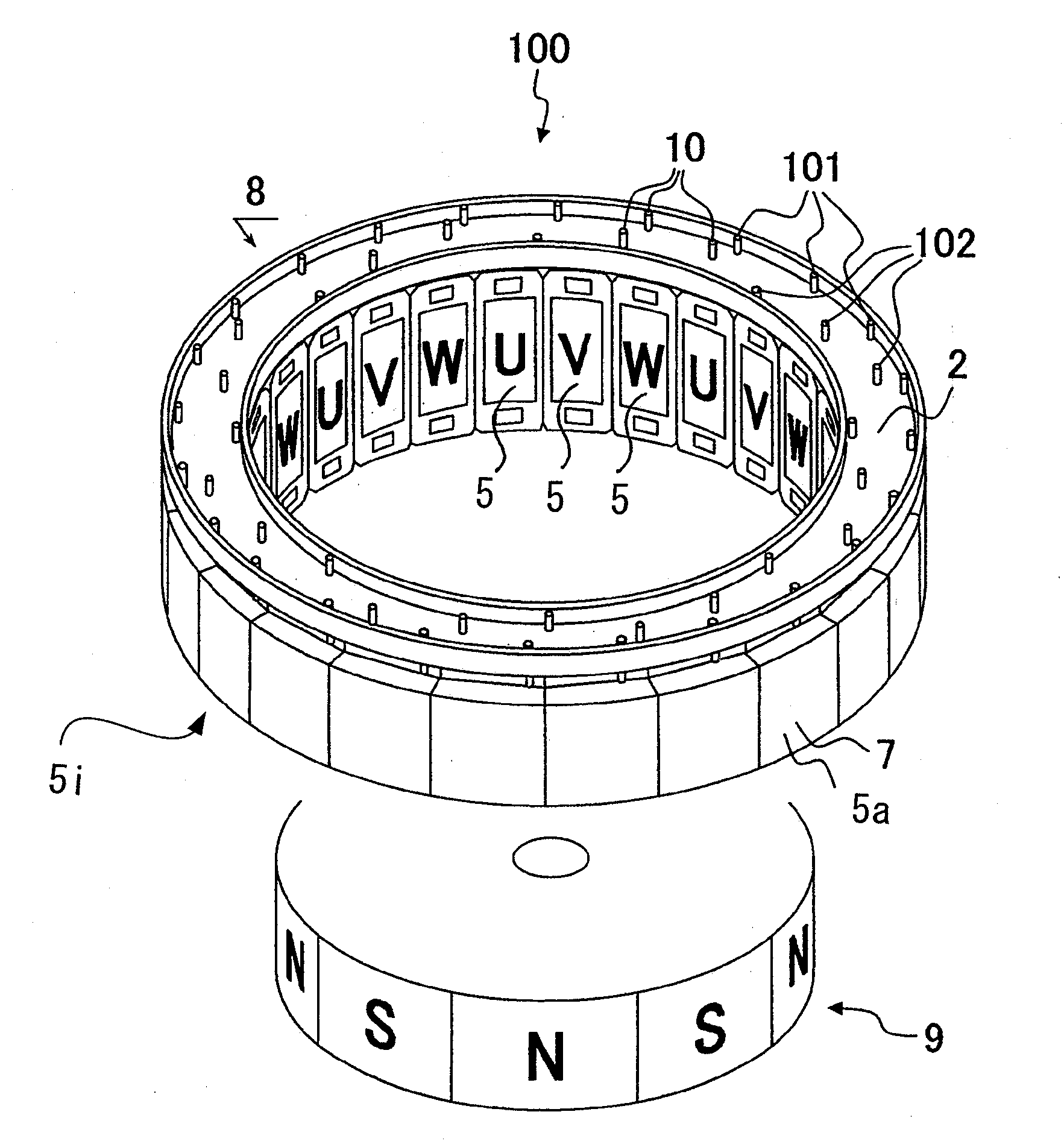
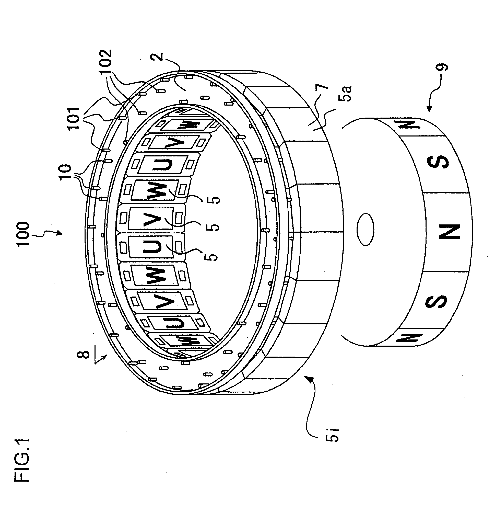
[0025]FIG. 1 is a perspective view of the rotating machine according to one embodiment of the present invention.

[0026]A rotating machine 100 includes a concentrated winding stator 8 and a rotor 9, arranged coaxially to each other. The rotor 9 includes a core and permanent magnets with respective N poles and S poles being arranged alternately on the side of the core.

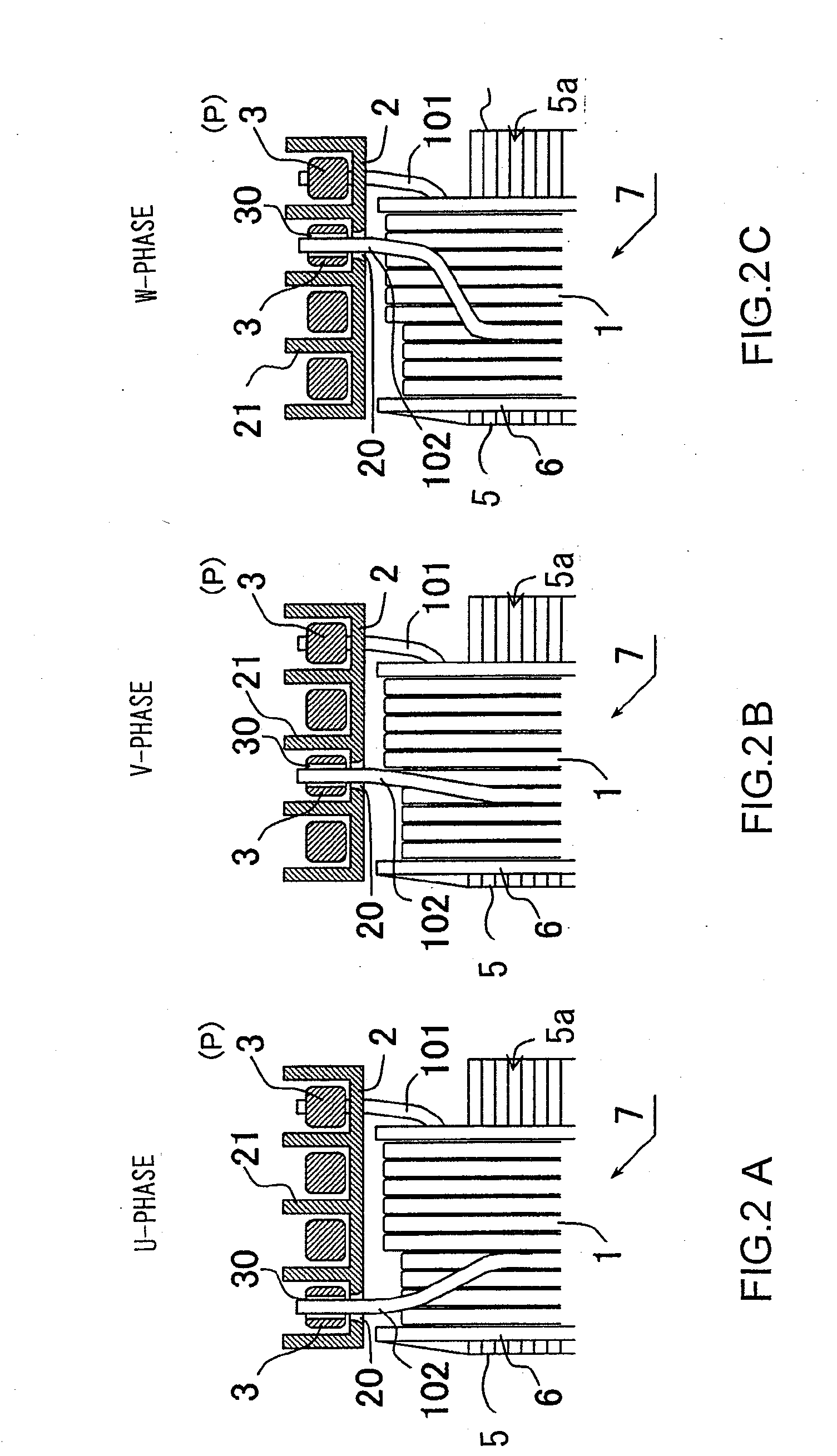
[0027]The concentrated winding stator 8 is constituted by a plurality of concentrated winding coils 7 that are assembled in an annular form. Each concentrated winding coil 7 is constituted by a core 5 of a divided core structure (see FIG. 5) and an insulation coated conductor wire 1 (FIG. 6) wound around the core 5. On a side perpendicular to the axial direction of the stator is formed a connection plate 2 of an annular form and are formed coil ends. A plurality of through-holes 20 (FIG. 3) are formed in the connection plate 2 and coil ends 10 are inserted therethrough. In the present embodiment, the number of concentrate...

second embodiment

[0044]In the first embodiment, the conductor 3 provided with connection hole 30 and the coil end 10 are simply welded. However, provision of a protrusion in the connection hole 30 can increase the junction area with the coil end 10. FIG. 7 is a perspective view that shows a connection part of the coil end 10 and the conductor 3a provided with a salient 33 according to a second embodiment.

[0045]A conductor 3a of the substantially rectangular cross-section is disposed on the surface of the connection plate 2, and the conductor 3a is formed of the salient 33 and of the connection hole 30. The coil end 10 is inserted through the connection hole 30 and a leading edge of the coil end 10 protrudes from the conductor 3. After the insertion, the coil end 10 and the surrounding of the connection hole 30 are fused by TIG welding to join the coil end 10 and the conductor3a. The length of the inner periphery in the axial direction increases by having formed the salient 33 to the conductor 3a to ...

third embodiment

[0046]Although the inner diameters of the through-hole 20 and of the connection hole 30 are made constant, respectively, Both may be provided with tapered parts, respectively, to make it easier to fabricate the stator.

[0047]FIG. 8 is a cross-section of a connection part between the coil end 10 and a conductor 3b formed of a connection hole and a tapered part in the connection hole. The conductor 3b is disposed on a connection plate 2a that is formed of a through-hole 40 with a tapered part. The through-hole 40 provided in the connection plate 2a has a part that corresponds to the through-hole 20 in the first embodiment and the second embodiment on the conductor 3b side (upper part in the figure), and subsequent thereto a tapered portion 401 of an angle of 30 degrees that opens on the other side of the conductor 3b, that is, on the entrance side of the coil end (lower side in the figure). On the other hand, a connection hole 50 is formed in the conductor 3b, and the connection hole p...


PUM


Abstract

The stator includes a plurality of concentrated winding coils disposed coupled into an annular form through yokes, and a plurality of conductors that couple the coil ends of the concentrated winding coils to each other in a multi-phase connection fashion. Conductors for a U-phase, a V-phase, a W-phase, and neutral points P are each formed of a plurality of holes for inserting therethrough coil ends and are substantially circular with different diameters, and are disposed on the same plane. A connection plate provided with a wall is inserted between the conductors and the concentrated winding coils. A rotating machine includes the above-mentioned stator and a rotor that is rotatable within the stator.

Description

INCORPORATION BY REFERENCE[0001]The disclosure of the following priority application is herein incorporated by reference: Japanese Patent Application No. 2007-096536 filed Apr. 2, 2007.BACKGROUND OF THE INVENTION[0002]1. Field of the Invention[0003]The present invention relates to stator for a rotating machine and a rotating machine using the same.[0004]2. Description of Related Art[0005]Forms of winding of a stator include concentrated winding where a wire is wound in a concentrated manner for each tooth of a magnetic pole to prepare a coil and distributed winding where a wire is wound over a plurality of slots, with coils of different phases or same phases being superposed at coil ends. The concentrated winding can be made with a reduced coil end as compared with the distributed winding, and is effective for downsizing and making the rotating machine highly effective. On the other hand, in the case of the distributed winding, the distribution of magnetic field at the inner periphe...

Claims


Application Information

Patent Timeline
Patent Type & Authority Applications(United States)
IPC IPC(8): H02K3/52
CPCH02K3/522
Inventor NAGANAWA, TAKASHIISHIGAMI, TAKASHIOBATA, KOJIUEDA, TOSHIAKIHOSHINO, KATSUHIRO
Owner HITACHI LTD
Why Eureka
Try Eureka