Gasification burner using high-pressure swirled air

a burner and high-pressure swirl technology, which is applied in the direction of pulverulent fuel combustion burners, combustion types, lighting and heating apparatus, etc., can solve the problems of many faults related to the cooling manner of the combustion chamber, the inability to meet environmental laws and regulations, and the excessive temperature difference between the interior of the combustion chamber and the outside of the air chamber, so as to minimize heat conduction

Inactive Publication Date: 2005-03-03
REMAKE +1
View PDF7 Cites 14 Cited by
  • Summary
  • Abstract
  • Description
  • Claims
  • Application Information

AI Technical Summary

Benefits of technology

[0013] Therefore, the present invention has been made in view of the above problems, and it is a first object of the present invention to provide a gasification burner using high-pressure swirled air which is designed to enable part

Problems solved by technology

In case that the sludge-state waste is buried in the land or at the bottom of the sea, it cannot be dissolved by bacteria since additives used in its treatment processes act to hinder effective action of the bacteria contained in the land or the sea water.
Further, when the sludge-state waste is discharged into the river or the sea, since the discharged waste contaminates the river or the sea, it is in conflict with environmental laws and regulations.
In such a conventional gasification burner, however, since the interior temperature of the combustion chamber is excessively raised in the process of burning, there are induced many faults related to cooling manners of the combustion chamber.
In case of the former air-cooling manner using a jacket-shaped air chamber defined throughout an outer periphery of the com

Method used


Image

  • Gasification burner using high-pressure swirled air
  • Gasification burner using high-pressure swirled air
  • Gasification burner using high-pressure swirled air

Examples


Embodiment Construction

[0038] Reference will now be made in greater detail to a preferred embodiment of the invention, an example of which is illustrated in the accompanying drawings.

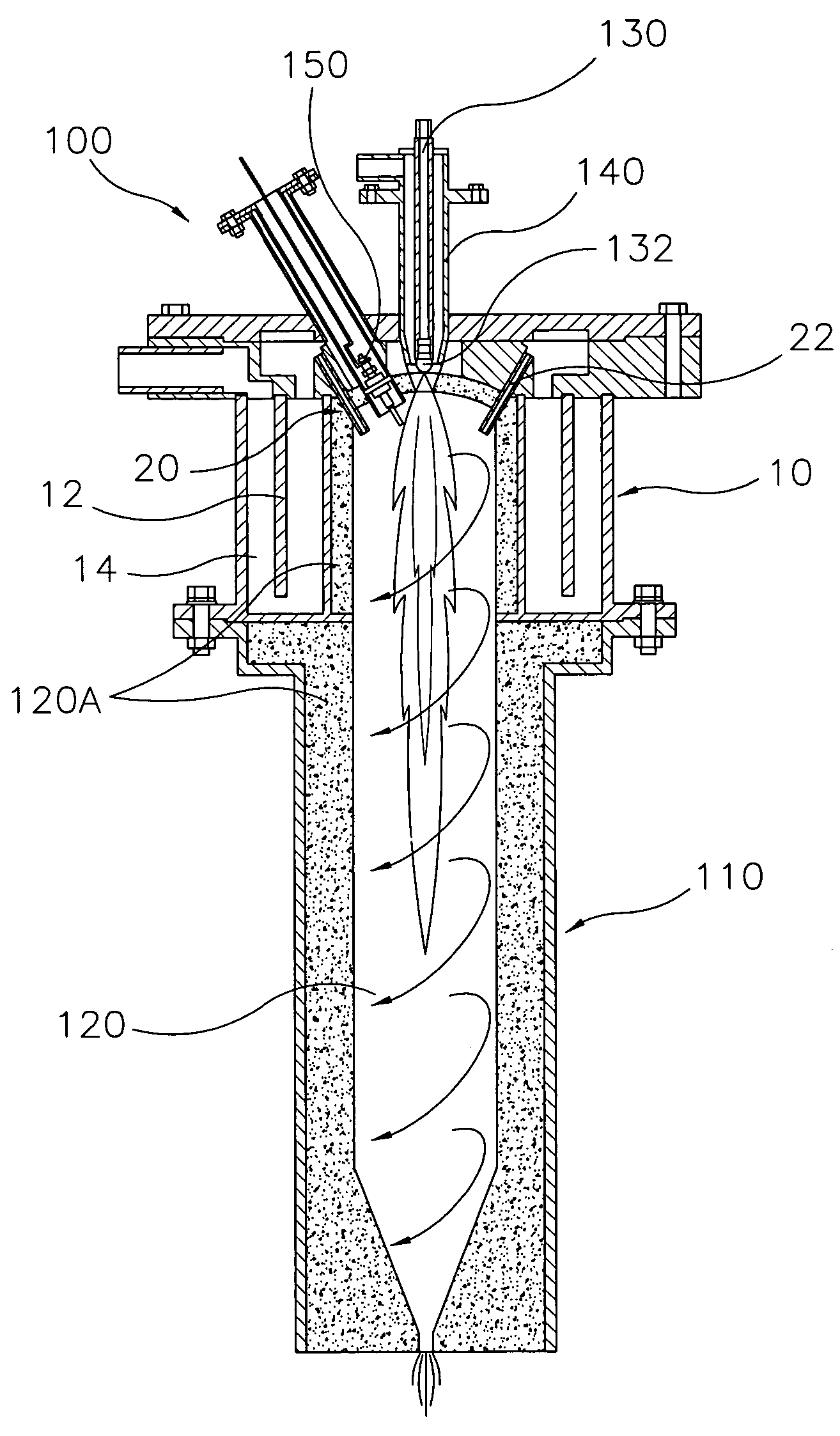
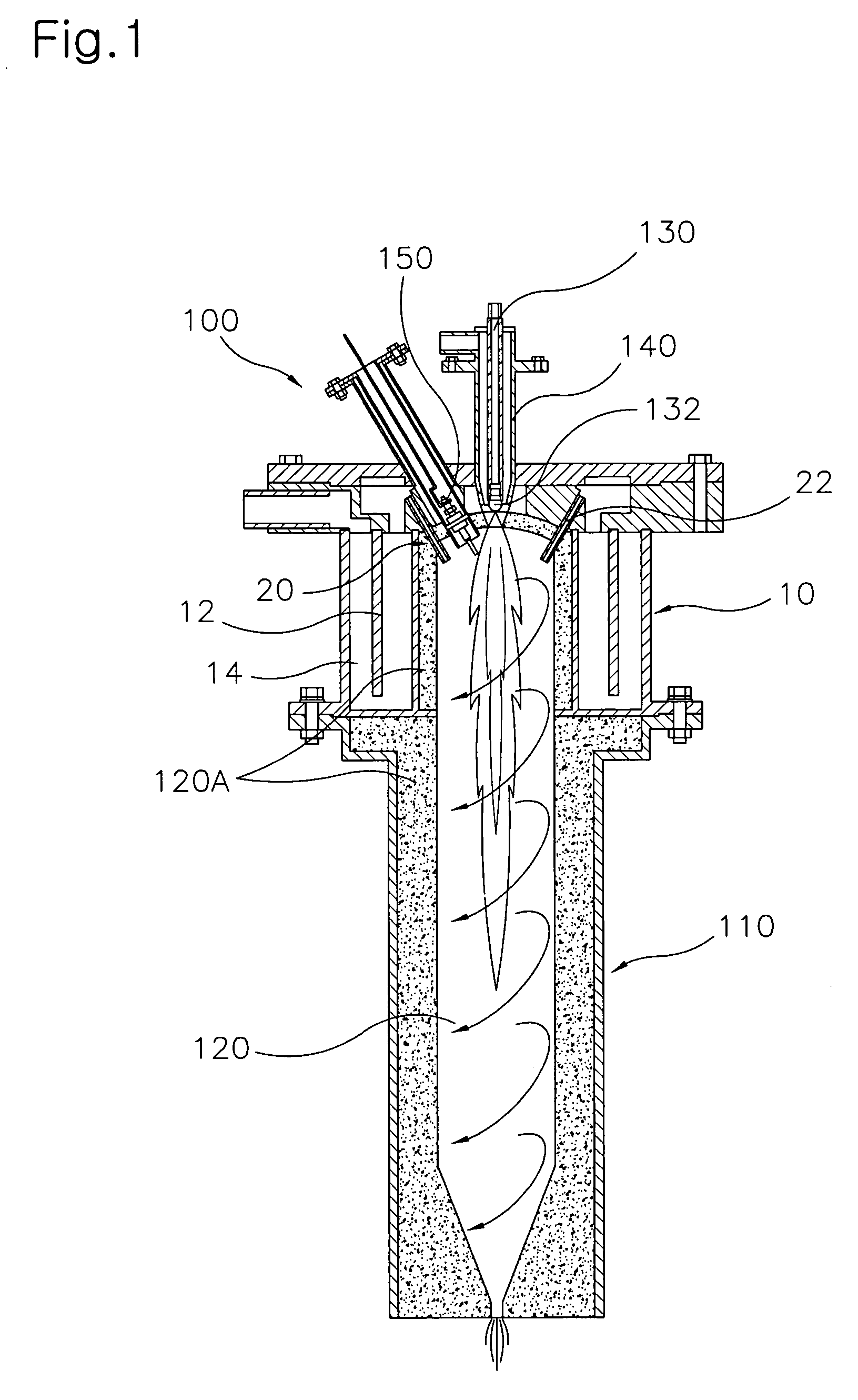
[0039]FIG. 1 is a schematic longitudinal sectional view illustrating a gasification burner in accordance with the present invention. FIG. 2 is a schematic plan view illustrating a swirled air feeder unit having air-jet nozzles shown in FIG. 1; [0040] As shown in FIGS. 1 and 2, in order to assure that, as a result of burning inside a combustion chamber at a temperature of approximately 1100 to 1500 degrees centigrade, high-temperature heat is discharged from one side of the combustion chamber at a high-pressure, and comes into instantaneous contact with the sludge-state waste, thereby allowing the sludge-state waste to be dehydrated, pulverized, and consequently gasified, there is used a gasification burner 100 comprising a housing 110, which internally defines a combustion chamber 120. Located at one side of the combustion c...


PUM


Abstract

Disclosed herein is a gasification burner using high-pressure swirled air. More particularly, the gasification burner using high-pressure swirled air is designed to enable partial cooling of a burner housing and to substantially prevent flames inside a combustion chamber from reaching an inner surface of the combustion chamber, resulting in an extension in the lifespan of the gasification burner. In the gasification burner comprising fuel feed pipe having a fuel injection nozzle, a combustion air feed pipe, an ignition plug, and a temperature sensor, which are located at one side of a combustion chamber defined in a burner housing, the gasification burner further comprises an air chamber unit, and a swirled air feeder unit. The air chamber unit is defined in an outer periphery of one end region of the housing where the fuel feed pipe and the combustion air feed pipe are mounted, and has a partition for providing the air chamber unit with a double-walled structure, defining an air feed channel. The swirled air feeder unit has a plurality of air-jet nozzles arranged along an inner periphery thereof near the fuel injection nozzle within the combustion chamber. The air-jet nozzles are obliquely disposed in a direction to communicate with the air feed channel.

Description

BACKGROUND OF THE INVENTION [0001] 1. Field of the Invention [0002] The present invention relates to a gasification burner using high-pressure swirled air, and more particularly to a gasification burner using high-pressure swirled air which is designed to enable partial cooling of a burner housing, and to substantially prevent flames inside a combustion chamber from reaching an inner surface of the combustion chamber, resulting in an extension in the lifespan of the gasification burner. [0003] 2. Description of the Related Art [0004] In general, aqueous waste, such as sewage slurry, food waste, etc., intrinsically contains a great deal of moisture. According to a solution proposed to process such aqueous waste, first, the aqueous waste is dehydrated until the moisture content thereof is reduced down to 70% to 90% via various processes including addition of wastewater treatment agents or activated sludge, sedimentation / concentration, mechanical-dehydration, or thermal-dehydration, et...

Claims


Application Information

Patent Timeline
IPC IPC(8): F23C3/00F23C7/00F23C7/02F23D14/78F23D11/24F23D14/22F23D14/24F23L1/00F23M5/00F23M11/04
CPCF23C3/00F23C7/002F23M2900/05004F23C2900/03005F23M11/045F23C7/02F23D14/22F23D11/24
Inventor TATSUMI, KINOSIHTA
Owner REMAKE
Why Eureka
Try Eureka