Thermal dispersion mass flow rate, material interface, and liquid level sensing transducer

a transducer and mass flow rate technology, applied in the field of thermodynamic and highly precise sensing transducers, can solve the problems of potting material in the transducer as a source of problems, unpredictable changes in heat transfer characteristics of the sensor, and air bubbles are often entrapped, so as to achieve no variation in output with time

Active Publication Date: 2017-06-06
FLUID COMPONENTS INTERNATIONAL
View PDF14 Cites 0 Cited by
  • Summary
  • Abstract
  • Description
  • Claims
  • Application Information

AI Technical Summary

Benefits of technology

[0019]A purpose of the disclosed embodiments is to control the heat transfer paths in thermal wells. Such control includes eliminating the need for potting of the RTD element or pressure forming the containing thermal wells. Additionally, the present concept substitutes a precision unchanging reproducibility thermal path between the RTD and the mounting surface of the thermal well in which the RTD is mounted. The precision, reproducible, and unchanging heat transfer path of the structure disclosed provides for high fidelity and consistent performance under all likely hostile service conditions so far as accurate, durable, and reproducible gas or fluid mass flow rate output, liquid level sensing, and interface sensing to and between non-miscible liquids and on non-liquids and slurries is concerned. For convenience, the concept of flowing fluid will be used herein, with the understanding that the structure applies equally to liquid level, non-miscible liquid interface sensing, and non-liquids and slurries.
[0022]The structure for the RTD wires to be connected externally to the usual flow rate indicators is also configured to minimize heat conduction which could affect the accuracy of the RTD signals. Thus, ambient influences are effectively eliminated.
[0023]Further, the thermal well proximal end and connection to typical mounting means is also configured to minimize unwanted heat transference otherwise related to the RTD signal and the fluid flow being sensed by employing long thin axially poorly thermally conductive and radially highly thermally conductive metal thermal wells. A highly thermally conductive ceramic cement to assure media temperature and thereby prevent any other temperature source from affecting the sensing RTDs is also used.
[0025]Another focus of the present concept is to provide a time consistent structure, that is, one which does not deteriorate or change its output over an appreciably long period of time. Further, by employing two identical thermal wells for the active and reference sensors, any change with time will likely track with both transducers so there would be no variation in output with time.

Problems solved by technology

However, in general and industry-wide, the potting material in the transducer has been a source of problems owing to changes in the heat transfer paths in the potting material, be it polymer, thermal grease, ceramic, or other material of means of mounting and, in particular, the mounting / heat transfer path to the process at other thermal sources to or from the temperature sensors.
Degradation or other changes in the potting compound results in unpredictable changes in 
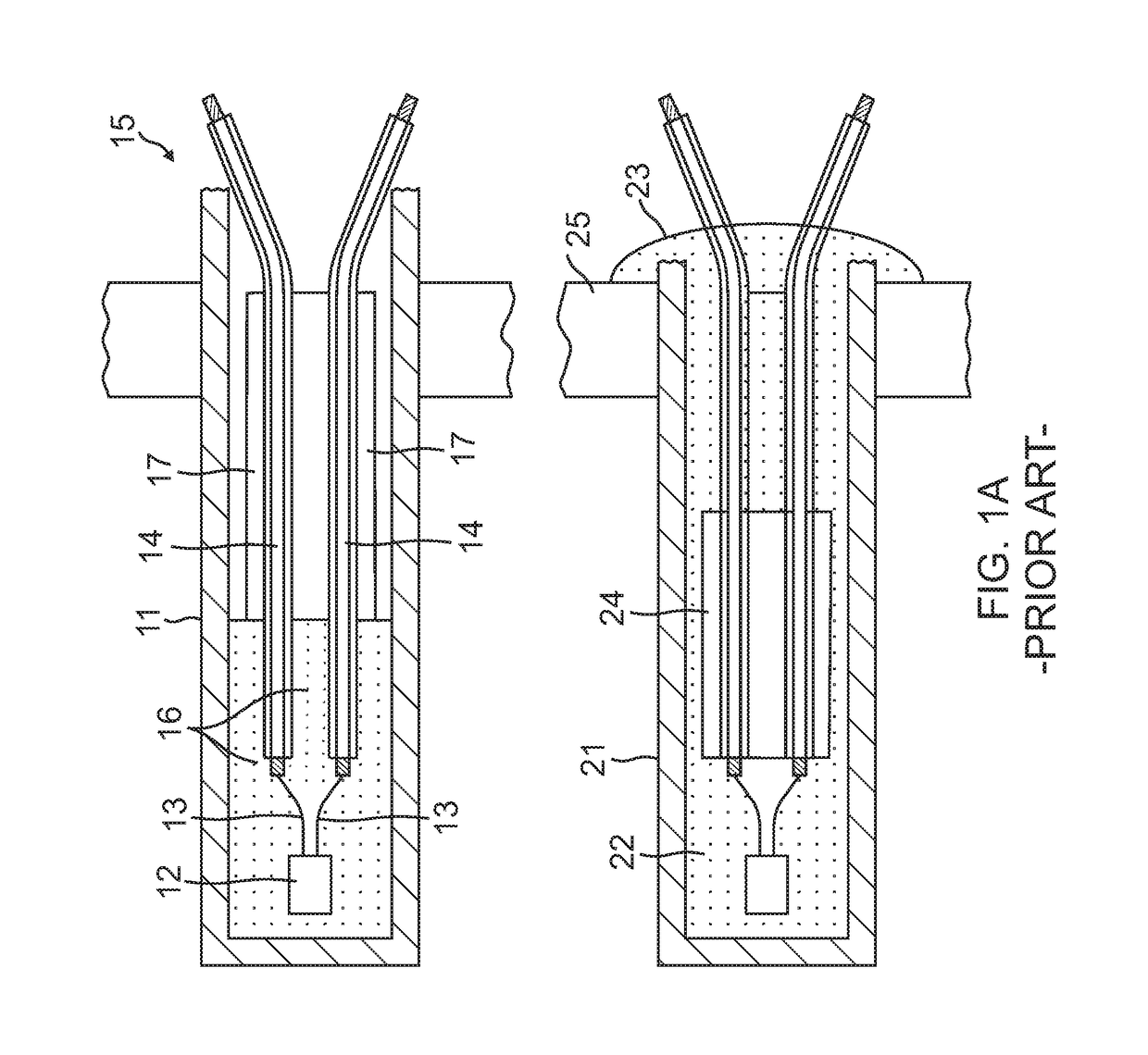
heat transfer characteristics of the sensor over time and temperature. FIG. 1 shows two exemplary thermal wells with large variations in the amount of potting material that may be used.
Consistency is, in fact, a bigger problem in that air bubbles are often entrained in the assembly process when potting material is added in the thermal well, and the RTD and its assembly of ceramic, tubing, and stranded copper leads are immersed in the semi-liquid potting material.
The same problem exists when a separate heater is used instead of self-heated RTDs.
This has been a significant problem because there were frequently multiple heat transfer paths as well as thermal variations in the fused joint affecting the unit-to-unit repeatability and the long term stability of the heat transfer paths.
Curing the potting material provides another instantaneous problem in that thorough curing of the polymer or ceramic potting is necessary.
This will also negatively affect the accuracy in service as compared to the calibration curves established for and sent by the manufacturer to the user with the sensor units.
As for particular types of potting material, which have been employed in such thermal transducers, thermal grease tends to dry out and turn to powder after several years of service, thereby causing a higher temperature to occur in the heated sensor.
This change has serious consequences for in-service accuracy, response time, and range, among other drawbacks.
The problem with this method is that when the hydro forming pressure is removed, the metal bounces back and thereby loosens the RTD which could subsequently move under service conditions.
Low electrical resistance is still another handicap to this scheme, among others.
Ceramic can shrink or expand over time and abraid or crack with repeated temperature cycling.
These conditions can lead to it gaps and, again, accuracy and response time deviations.
Polymers such as epoxy and silicone-based plastics degrade and age with temperature and time.
In addition, to thermal transducer inaccuracies resulting from potting problems as set out above, there are other sources of sensor output inaccuracies.
Variations in the ambient (external) temperature and heat transfer conditions have been a source of error.
When required to function in extreme weather conditions, where temperatures may range from as low as −65° F. to as high as +150° F., a conventional thermal sensor will be subject to erroneous output directly related to such conditions.
Apart from the ambient thermal conditions above, errors in sensor output may not be permanent and some of them may be ameliorated by recalibration.
However, if recalibration is frequently required, the trust in the output of the sensor, and its operational value, are severely diminished.
Depending upon the equipment and circumstances recalibration may entail a significant disruption of an important process.
Since the subject matter here is thermal sensors it is generally conceded that accurate temperature measurement is one of the most difficult physical measurements to make.
The problem is compounded in flow switches and transmitters, and liquid-to-liquid interface sensors, because what is being measured are heat transfer rates, which is a much more difficult measurement than temperature alone.
Accurate temperature representation is difficult but is a necessary component of heat transfer measurement.
However, in this subject area of technology, precise temperature measurements, per se, are not required and temperature sensing devices are generally not relevant to the concept which is the subject of this disclosure.
Relatively thick walls of the metal thermal wells and conductivity (thermal) from the RTDs to the variations in temperature of surfaces tend to produce errors in the accurate temperature sensing of the RTDs or other suitable temperature sensors such as thermocouples, among others.
Thermal conductivity along, and axial moist air and its corrosive effects by leakage between, stranded copper lead wires connected to the short and fine RTD lead wires is another source of error.

Method used


Image

  • Thermal dispersion mass flow rate, material interface, and liquid level sensing transducer
  • Thermal dispersion mass flow rate, material interface, and liquid level sensing transducer
  • Thermal dispersion mass flow rate, material interface, and liquid level sensing transducer

Examples


Embodiment Construction

[0019]A purpose of the disclosed embodiments is to control the heat transfer paths in thermal wells. Such control includes eliminating the need for potting of the RTD element or pressure forming the containing thermal wells. Additionally, the present concept substitutes a precision unchanging reproducibility thermal path between the RTD and the mounting surface of the thermal well in which the RTD is mounted. The precision, reproducible, and unchanging heat transfer path of the structure disclosed provides for high fidelity and consistent performance under all likely hostile service conditions so far as accurate, durable, and reproducible gas or fluid mass flow rate output, liquid level sensing, and interface sensing to and between non-miscible liquids and on non-liquids and slurries is concerned. For convenience, the concept of flowing fluid will be used herein, with the understanding that the structure applies equally to liquid level, non-miscible liquid interface sensing, and non...


PUM


Abstract

A thermal mass dispersion flow rate sensing transducer and transducer assembly or instrument for improved functional life of the transducer without degradation in sensing accuracy. Several aspects of the transducer components and structure reduce thermal leakage within the transducer so the sensor (RTD) output signal is accurately transmitted to the signal processor, resulting in precise ΔT determinations and consequent precise determinations of mass flow rate of the fluid flowing in the conduit. Additionally, the same components and structure also have long life without appreciable degradation, thereby delaying any basis for the need for recalibration of the instrument.

Description

FIELD OF THE INVENTION[0001]This concept relates generally to thermal dispersion, highly precise sensing transducers and, more particularly, to innovations relating, in part, to reducing thermal leakage from or to the sensor, and providing higher signal to noise ratio, which improve the performance of the transducer in terms of accuracy, response time, cost, power consumed, durability, repeatability from instrument to instrument, which is accurate reproduction or fidelity, and repeatability of the same instrument over time, correcting what is generally referred to as “sensor drift.”DISCUSSION OF THE PRIOR ART[0002]Thermally-based fluid flow, liquid level, and fluid interface transducers or sensors employ the well-known and long established principle that is heated sensor will have different characteristics with temperature changes. A resistance temperature detector (RTD) will have a temperature change as the process temperature of the fluid in which the sensor is immersed or the vel...

Claims


Application Information

Patent Timeline
Patent Type & Authority Patents(United States)
IPC IPC(8): G01F1/69G01F23/22
CPCG01F1/69G01F23/22G01F1/684G01F15/006G01F15/02G01F23/248G01K1/20
Inventor MCQUEEN, MALCOLM M.
Owner FLUID COMPONENTS INTERNATIONAL
Why Eureka
Try Eureka