Flexible support apparatus for superconducting magnet in superconducting rotating machine

a superconducting magnet and rotating machine technology, applied in the direction of superconducting magnets/coils, magnetic bodies, magnetic circuit shapes/forms/construction, etc., can solve the problems of reducing the heat load of cooling superconducting coils, weakening the superconducting application equipment on a force arising coil or external force, etc., to minimize heat load, minimize heat conductivity, minimize heat load

Active Publication Date: 2019-06-11
CHANGWON NAT UNIV IND ACAD COOPERATION CORPS
View PDF8 Cites 0 Cited by
  • Summary
  • Abstract
  • Description
  • Claims
  • Application Information

AI Technical Summary

Benefits of technology

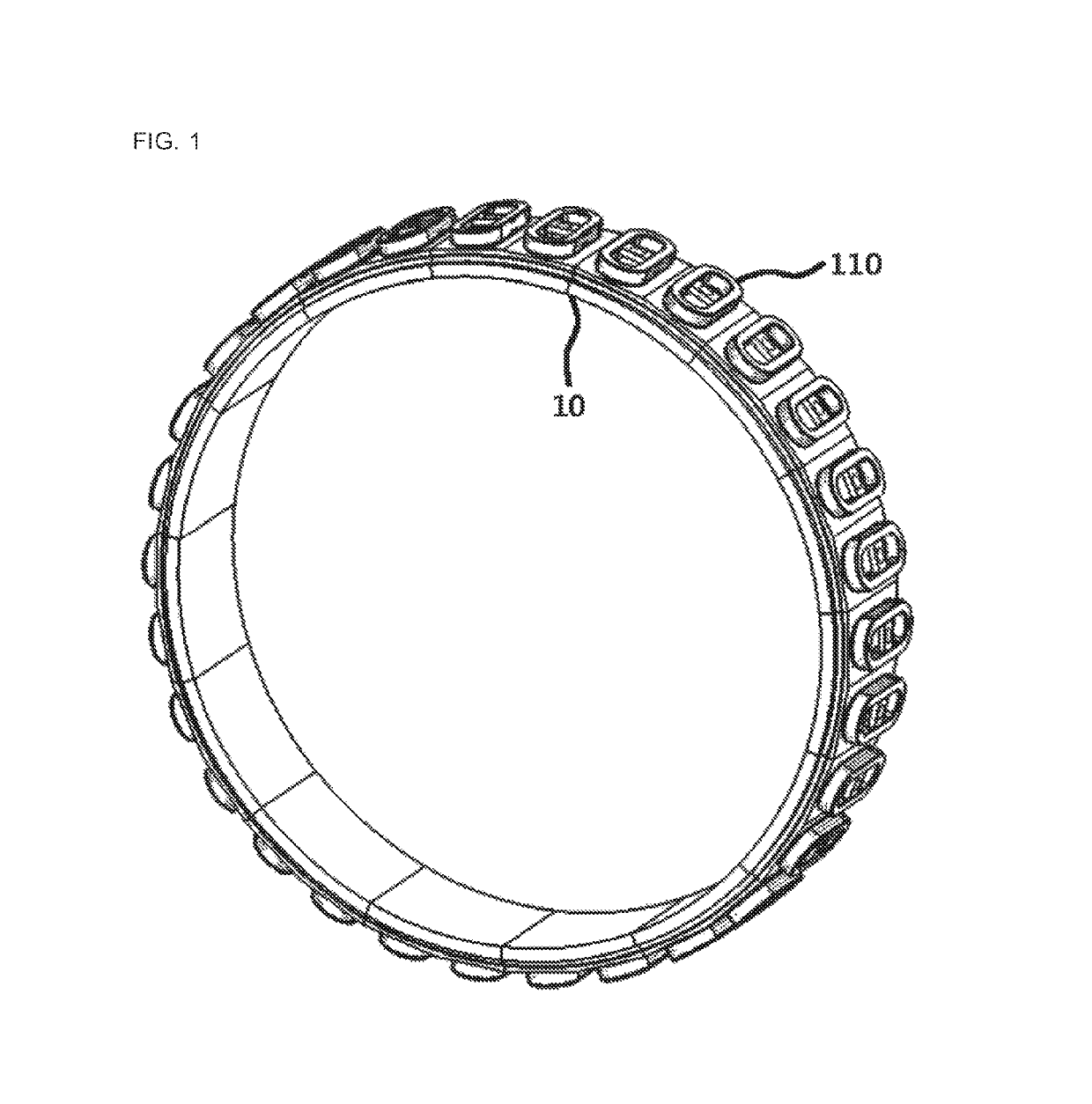
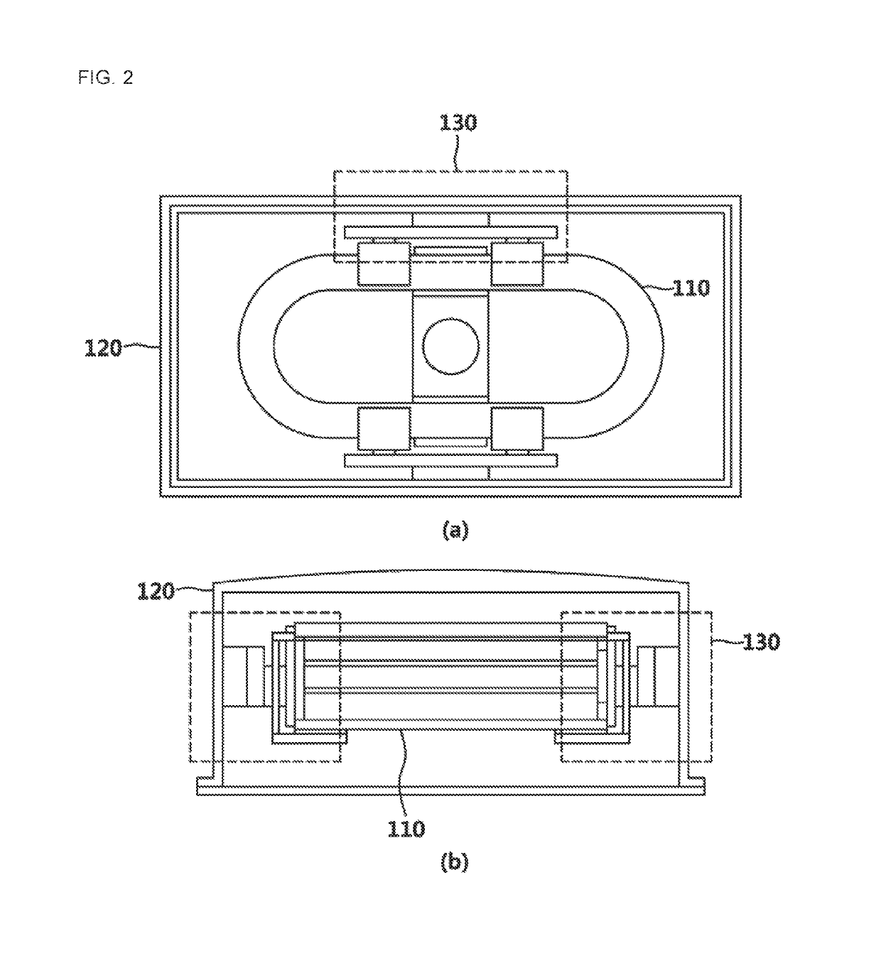
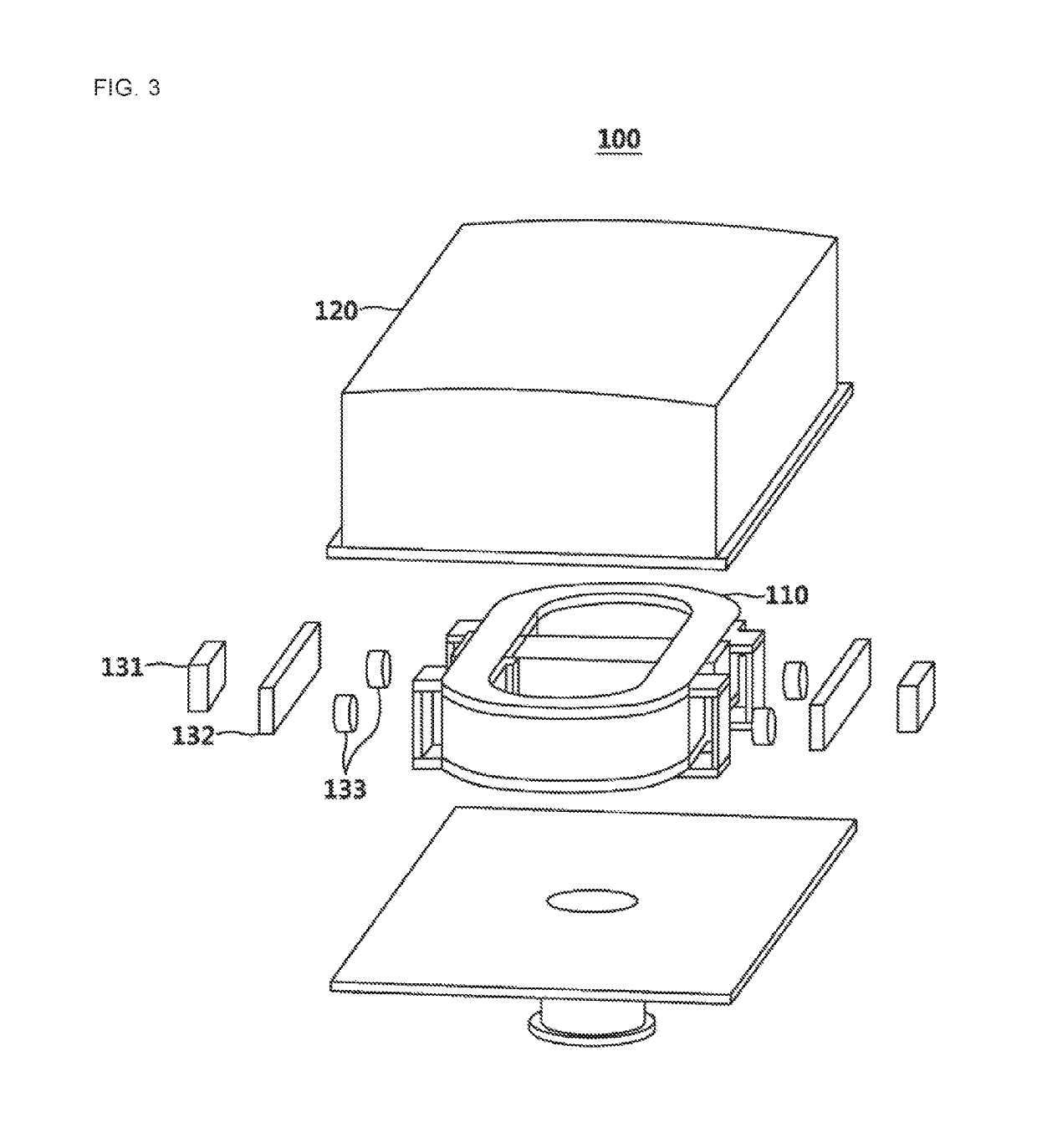
[0007]Examples of the present disclosure are provided to introduce a flexible support apparatus for superconducting magnet in superconducting rotating machine that is capable of supporting a superconducting magnet as well as minimizing heat conduction via the structure of a plurality of supports with flexibility in order to protect or support the superconducting magnet from torque or Lorentz force that results from the rotational motion of superconducting rotating machine.
[0008]Examples of the present disclosure are provided to introduce a flexible support apparatus for superconducting magnet in superconducting rotating machine that is capable of releasing a mechanical stress and a force that periodically changes and minimizing a heat load via the structure of supports having flexibility and minimized heat conductivity, regarding high mechanical stress that superconducting rotor has and force that periodically changes, and minimized heat conductivity.

Problems solved by technology

However, as being high magnetic field and carrying high current, there is the disadvantage that superconducting application equipment is weak on a force arising coil or external force.
In addition, regarding superconductors, there is the problem that a heat load for cooling superconducting coils needs to be minimized.

Method used


Image

  • Flexible support apparatus for superconducting magnet in superconducting rotating machine
  • Flexible support apparatus for superconducting magnet in superconducting rotating machine
  • Flexible support apparatus for superconducting magnet in superconducting rotating machine

Examples


Embodiment Construction

[0029]The following detailed description is provided to assist the reader in gaining a comprehensive understanding of the methods, apparatuses, and / or systems described herein. However, various changes, modifications, and equivalents of the methods, apparatuses, and / or systems described herein will be apparent after an understanding of the disclosure of this application. For example, the sequences of operations described herein are merely examples, and are not limited to those set forth herein, but may be changed as will be apparent after an understanding of the disclosure of this application, with the exception of operations necessarily occurring in a certain order. Also, descriptions of features that are known in the art may be omitted for increased clarity and conciseness.

[0030]The features described herein may be embodied in different forms, and are not to be construed as being limited to the examples described herein. Rather, the examples described herein have been provided mer...


PUM

PropertyMeasurementUnit
flexibleaaaaaaaaaa
superconductingaaaaaaaaaa
heat conductivityaaaaaaaaaa

Abstract

The present disclosure relates to a flexible support apparatus for superconducting magnet in superconducting rotating machine. The present disclosure relates to a flexible support apparatus for superconducting magnet in superconducting rotating machine that includes a superconducting magnet that is located in a rotor body of a superconducting rotating machine, a vacuum container that internally stores the superconducting magnet, a first support that supports the superconducting magnet by being internally attached to the vacuum container, a third support that supports the superconducting magnet by being externally attached to the superconducting magnet, and a second support that is located between the first support and the second support and that supports the superconducting magnet by including a flexible material.

Description

CROSS-REFERENCE TO RELATED APPLICATIONS[0001]This application claims the benefit under 35 U.S.C. 119(a) of Korean Patent Application No. 10-2016-0173875 filed on Dec. 19, 2016 in the Korean Intellectual Property Office, the entire disclosure of which is incorporated herein by reference for all purposes.BACKGROUND1. Field[0002]The present disclosure relates to a flexible support apparatus for superconducting magnet in superconducting rotating machine. In particular, the present disclosure relates to a flexible support apparatus for superconducting magnet in superconducting rotating machine that is capable of supporting a superconducting magnet as well as minimizing heat conduction via the structure of a plurality of supports with flexibility in order to protect or support the superconducting magnet from torque or Lorentz force that results from the rotational motion of superconducting rotating machine.2. Description of Related Art[0003]Superconductors having zero electrical resistanc...

Claims


Application Information

Patent Timeline
Patent Type & Authority Patents(United States)
IPC IPC(8): H02K1/28H01F41/04H01F6/06H02K15/03H02K7/08H02K1/27
CPCH02K1/28H01F6/06H02K1/27H02K15/03H02K7/086Y02E40/62H01F41/048H02K55/04Y02E40/60H10N60/81
Inventor PARK, MIN WONYU, IN KEUNSUNG, HAE JINGO, BYEONG SOOSHIN, HYUN KYUNG
Owner CHANGWON NAT UNIV IND ACAD COOPERATION CORPS
Why Eureka
Try Eureka