Emergency oxygen or other gas supply system

a gas supply system and emergency technology, applied in emergency oxygen systems, emergency apparatuses, seating arrangements, etc., to achieve the effect of reducing the amount of space required

Inactive Publication Date: 2005-06-02
INTERTECHN +1
View PDF8 Cites 13 Cited by
  • Summary
  • Abstract
  • Description
  • Claims
  • Application Information

AI Technical Summary

Benefits of technology

[0025] It is an additional optional, non-exclusive object of the present invention to provid

Problems solved by technology

However, unlike the components of the Schumacher '415 patent, the pod assemblies

Method used


Image

  • Emergency oxygen or other gas supply system
  • Emergency oxygen or other gas supply system
  • Emergency oxygen or other gas supply system

Examples


Embodiment Construction

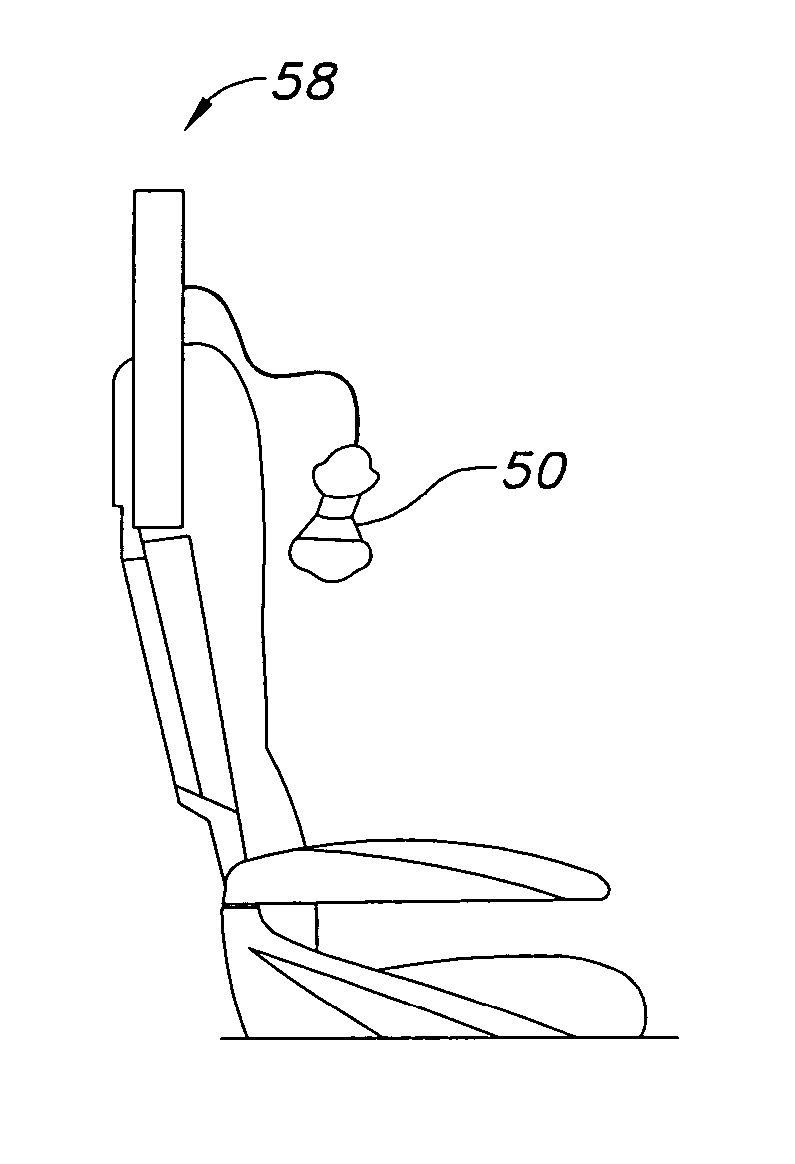
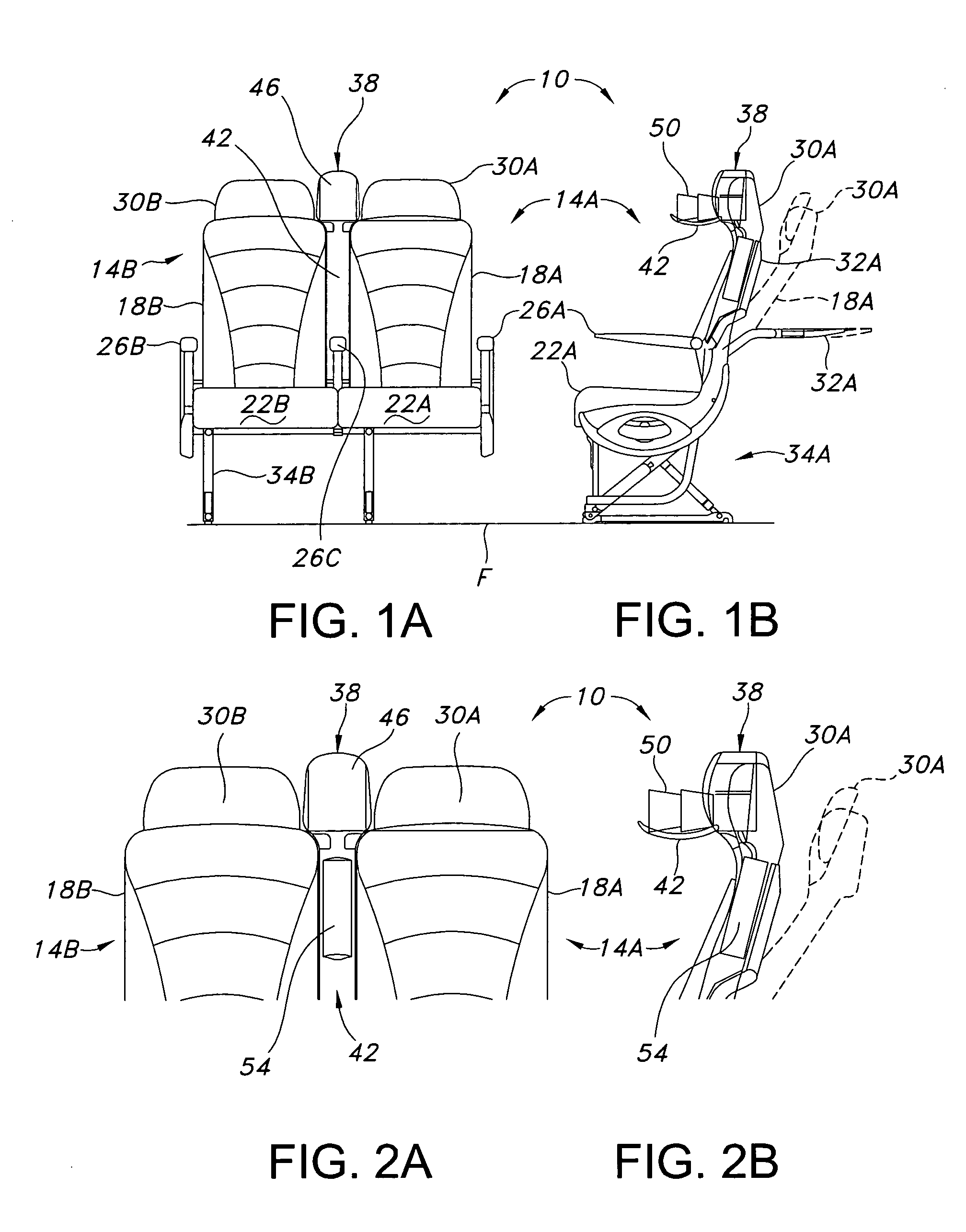
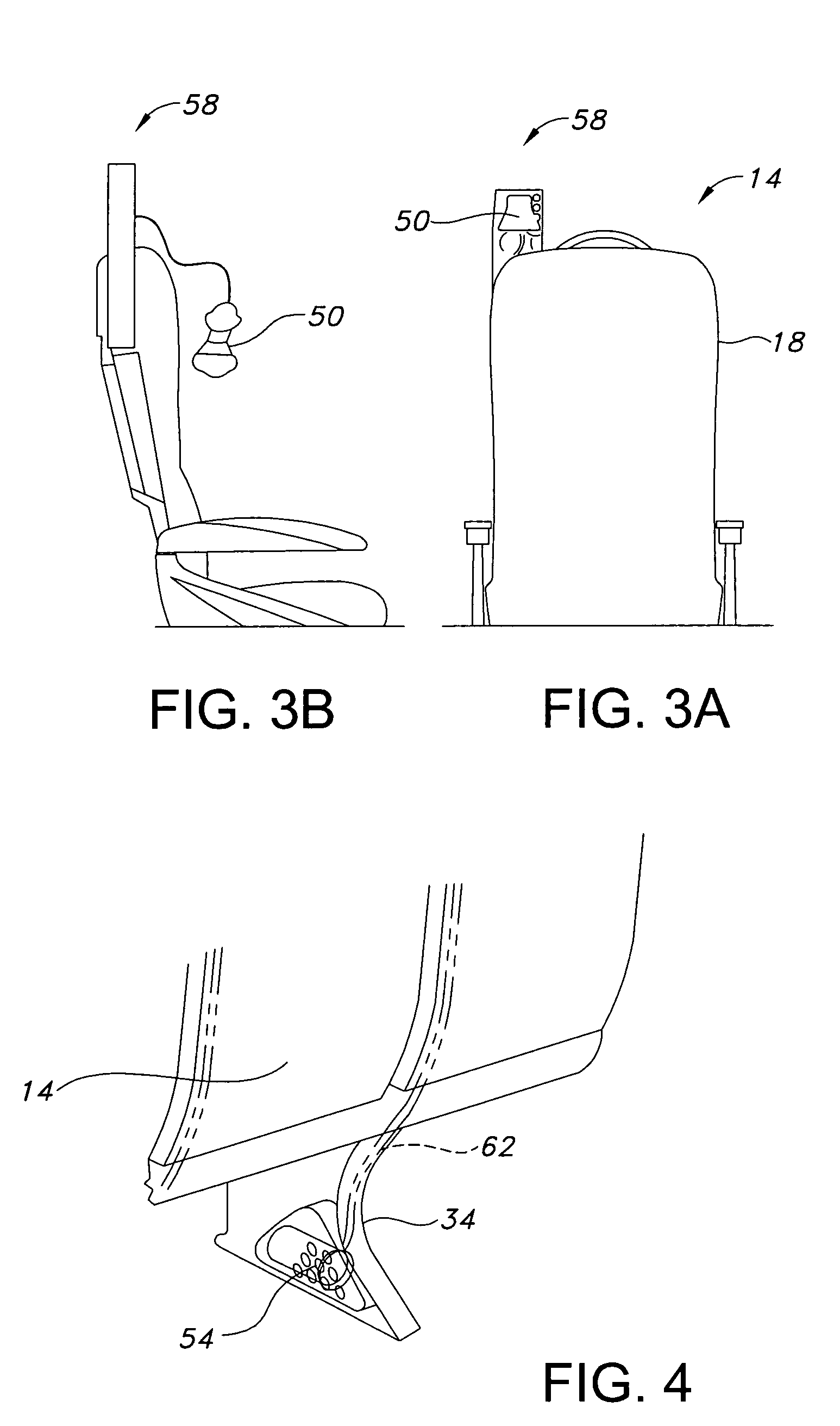
[0037] Depicted in FIGS. 1A-B and 2A-B are portions of seat cluster 10 consistent with aspects of the present invention. As shown in these figures, cluster 10 comprises seats 14 (denoted 14A and 14B), each designed for a single human occupant. However, those skilled in the relevant field understand that cluster 10 may contain fewer or more seats 14 than the two illustrated in FIGS. 1-2.

[0038] Each of seats 14A and 14B may include components common to seats presently in use in vehicles (particularly commercial aircraft). Referring to seat 14A, for example, it may include seat back 18A, seat bottom 22A, and optionally at least one arm rest 26A. Also detailed in FIGS. 1-2 for seat 14A are head rest 30A, (rearwardly-extending) tray table 32A, and leg assembly 34A designed for attachment to floor F of an aircraft or other cabin. Similarly, seat 14B may include some or all of seat back 18B, seat bottom 22B, arm rest 26B, head rest 30B, a tray table (not shown), and leg assembly 34B (only...


PUM


Abstract

Systems for supplying emergency oxygen or other gases to persons are addressed. The systems may include pod assemblies mounted on fixed-position masts between or adjacent passenger seats or pop-up modules installed within upper portions of seat backs. The pod assemblies and pop-up modules additionally may include other passenger-service equipment. Also optionally included in the systems are modular central gas supplies and alternative oxygen mask designs for passengers.

Description

CROSS-REFERENCE TO RELATED APPLICATION [0001] This application claims the benefit of U.S. Provisional Application No. 60 / 518,499 filed on Nov. 7, 2003, the contents of which are incorporated herein by reference.FIELD OF THE INVENTION [0002] This invention relates to systems for supplying gases and more particularly, but not exclusively, to systems furnishing oxygen in emergencies to passengers onboard vehicles such as, but not limited to, commercial aircraft. BACKGROUND OF THE INVENTION [0003] U.S. Pat. Nos. 4,609,166 to Brennan and 5,154,374 to Beroth, incorporated herein in their entireties by this reference, disclose emergency oxygen-supply systems for aircraft. Included in the systems are oxygen-generating canisters located beneath seat cushions of commercial aircraft seats and oxygen masks positioned within the backs of the seats. Because the masks are positioned within seat backs, access to them is available only from the rears of the seats, so that the masks are intended for ...

Claims


Application Information

Patent Timeline
IPC IPC(8): B64D11/00B64D11/06
CPCB64D11/00B64D11/0629B64D2231/025B64D11/06B64D11/0632B64D11/064
Inventor POZZI, ALEXANDER N.CARBARY, SCOTT F.BENTLEY, PAUL R.COUTU, MARC ANDREGRETER, VINCENT
Owner INTERTECHN
Why Eureka
Try Eureka