Mail sorting and distributing transfer system

Inactive Publication Date: 2005-06-02
TSUBAKIMOTO CHAIN CO
View PDF16 Cites 1 Cited by
  • Summary
  • Abstract
  • Description
  • Claims
  • Application Information

AI Technical Summary

Benefits of technology

[0013] Since the mail sorting and distributing transfer system of the present invention includes peculiar system configurations, the following special effects can be achieved. That is, in the mail sorting and distributing transfer system of the present invention since the conveyor basket includes an inner circumferential side carriage and an outer circumferential side carriage, it can stably, smoothly circulate on an inner circumferential side rail and an outer circumferential side rail constructed on a mail sorting line while hanging the conveyor basket by both sides in a carried state. Further, since the mail sorting and distributing transfer system of the present invention does not receive the influence of a rotational moment generated by a conveyor basket itself and the self weight of the mail, it can reliably transfer the mail from a transfer basket to conveyor basket and effect conveying power savings.
[0014] The mail sorting and distributing transfer system of the present invention provides the additional effect that since the inner circumferential side carriages are connected to each other through a connecting bar with a traveling roller and a guide roller being provided, the outer circumferential side carriage is separated from a connecting element for conveyor baskets and absorbs the path difference between the inner circumferential side and outer circumferential side generated during circular traveling to be able to exert a smooth circular operation, and that operations such as a mail sorting operation and a maintenance operation from the outer circumferential side carriage side can be easily attained.
[0015] Further, the mail sorting an

Problems solved by technology

Thus, transferable time therebetween is short, and when the transfer timing is shifted even a little, transfer failure

Method used


Image

  • Mail sorting and distributing transfer system
  • Mail sorting and distributing transfer system
  • Mail sorting and distributing transfer system

Examples


Example

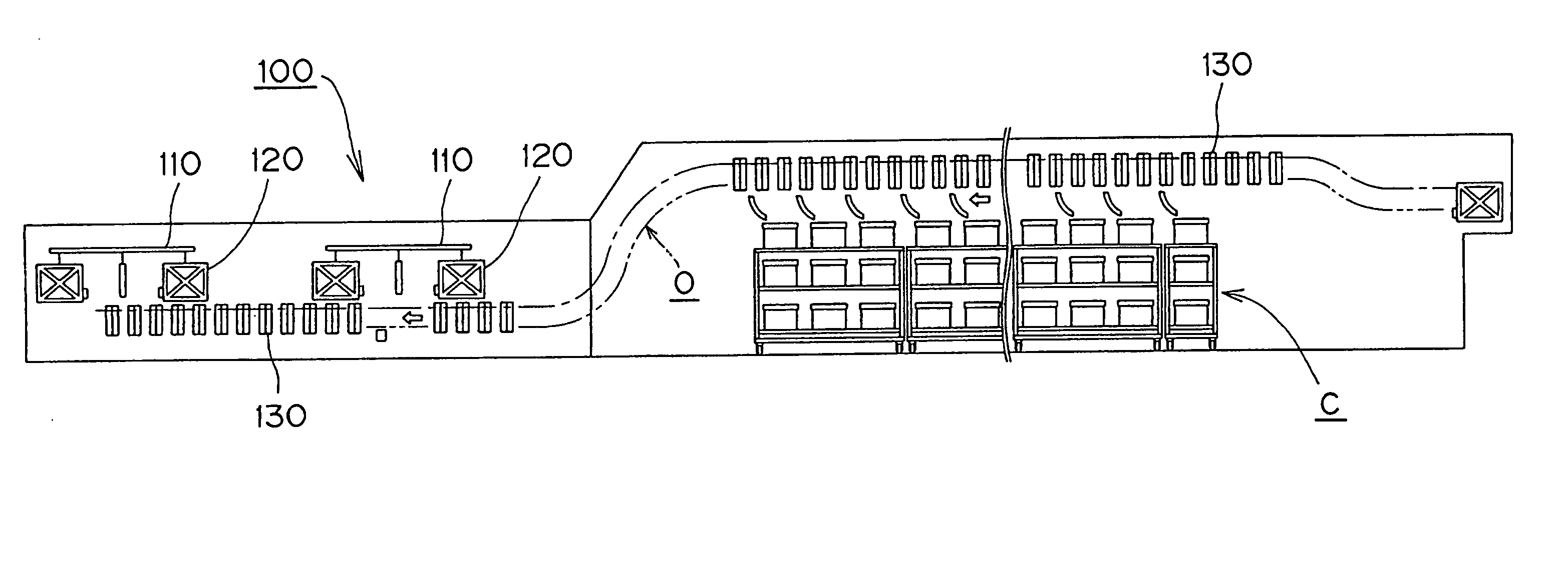
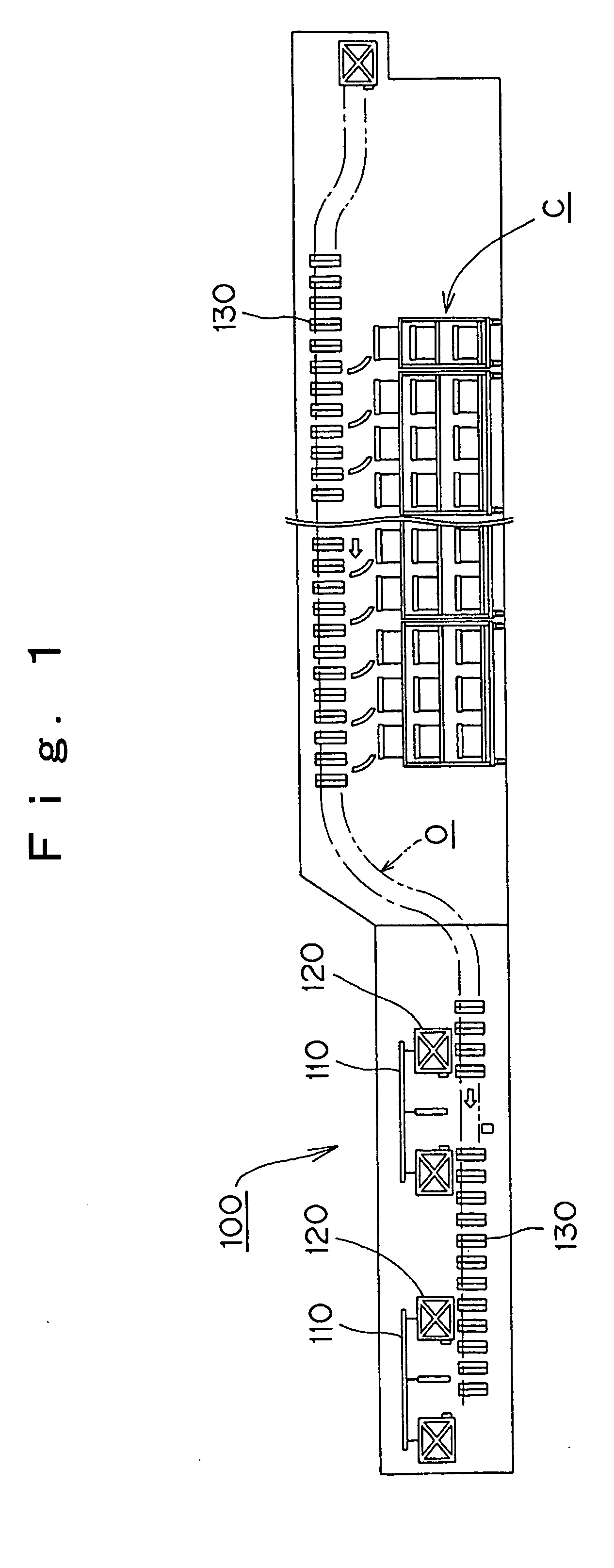
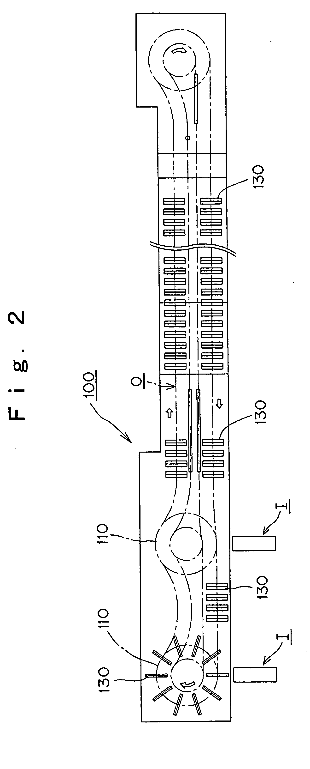
[0025] A mail sorting and distributing transfer system 100 embodying the present invention is shown in FIGS. 1 and 2. It receives mail supplied from one of two mail charging lines I (FIG. 2), which includes a mail sorting receiver's data reader and the like, through a transfer basket 120 provided on an outer circumferential edge of a mail sorting and distributing turn table 110. The transfer basket 120 transfers the mail to a conveyor basket 130 on the mail sorting line O.

[0026] It is noted that two mail sorting and distributing transfer systems 100 in FIGS. 1 and 2, are provided on a supply side on the mail sorting line O in consideration of the types of mail, efficiency of sorting operation and the like. Further, the reference character C in FIG. 1 denotes mail recovery boxes for sorting and recovering mail from the conveyor basket 130, and the arrow denotes a movement direction of the conveyor basket 130, which is moved just under the transfer basket 120 in synchronization with ...


PUM


Abstract

A mail sorting and distributing transfer system, which smoothly conveys mail on a mail sorting line having a compound curve whose line is not in a plane, but is three-dimensional, whereby the mail can be reliably transferred to a conveyor basket and conveying power savings are achieved. The system 100 receives mail in a transfer basket 120 hung at an outer circumferential edge of a mail sorting and distributing turn table 110 and transfers the mail through a transfer port 122 to a conveyor basket 130, which circulates on a mail sorting line O. The transfer basket 130 includes an inner circumferential side carriage 131 and an outer circumferential side carriage 132, which respectively travel on an inner circumferential side rail 142 and an outer circumferential side rail 143 of the mail sorting line O while hanging a basket body 133 by both sides in a carried state.

Description

RELATED APPLICATION [0001] This application claims the priority of Japanese Application No. 2003-398020, filed Nov. 27, 2003. FIELD OF INVENTION [0002] The present invention relates to a mail sorting and distributing conveyor system, which receives mail supplied from a mail charging line provided with a mail sorting receiver's data reader or the like, and transfers the mail to conveyor baskets on the mail sorting line for sorting the mail in accordance with the mail sorting receiver's data. BACKGROUND OF THE INVENTION [0003] A conventional mail sorter includes a synchronous transfer section, which charges mail into a conveyor box while mail holder sections are shifted in synchronization with the movement of the conveyor boxes for sorting the mail, so that the mail holder sections are adapted to transfer the mail to the conveyor boxes while a fixed section is moving in synchronization with the movement of the conveyor boxes. [0004] Such a conventional mail sorter must transfer mail t...

Claims


Application Information

Patent Timeline
IPC IPC(8): B07C3/02B07C3/00B07C3/04B07C3/08
CPCB07C3/082B07C3/008Y10S209/90
Inventor UMEZAWA, KENJIOKAMOTO, SHOGOASUKAI, MASAHIROYOSHIDA, MASAHIKO
Owner TSUBAKIMOTO CHAIN CO
Why Eureka
Try Eureka