Electrical junction box

Inactive Publication Date: 2005-06-02
SUMITOMO WIRING SYST LTD
View PDF15 Cites 10 Cited by
  • Summary
  • Abstract
  • Description
  • Claims
  • Application Information

AI Technical Summary

Benefits of technology

[0011] According to the above construction, because the bolt-joining portion between the input terminal section of the fusible link having the bus bar and the terminal coupled to the end of the electrical power source cable is disposed not within the body casing but above the upper surface of the body casing, the bolt-joining portion is exposed merely by removing the upper cover from the body casing and the bolt is released when removing the fusible link, thereby facilitating a work of removing the fusible link.
[0012] Also, because the bolt-joining portion is disposed at the position higher than the upper surface of the body casing or at the position opposite to the cutout provided in the body casing and the handling space for fastening or releasing the bolt is defined at a position opposite to the bolt-joining portion, the bolt can be readily removed and drawn out the fusible link from the body casing.
[0013] Also, because the bolt can fasten the input terminal section of the fusible link on the terminal coupled to the end of the electrical power source cable while the fusible link is contained in the body casing, fastening or releasing the bolt can be facilitated.
[0016] According to the above construction, because the bolt-joining portion of the input terminal section of the fusible link extends horizontally along the upper surface of the body casing of the electrical junction box, that is, the bolt-joining portion projects to be directed upward, fastening or releasing the bolt is facilitated.
[0017] Also, because it is not necessary to arrange the electrical power source cable from a lower part of the body casing to an upper part of the body casing and the thin intermediate bus bar interconnects the input terminal section of the fusible link and the terminal coupled to the end of the electrical power source cable, it is possible to reduce a space and to make a compact electrical junction box.
[0022] It will be apparent from the foregoing that according to various exemplary embodiments of the invention because the bolt-joining portion between the input terminal section of the fusible link having the bus bar and the terminal coupled to the end of the electrical power source cable is disposed not within the body casing but above the upper surface of the body casing, the bolt-joining portion is exposed merely by removing the upper cover from the body casing and the bolt is released when removing the fusible link, thereby facilitating a work of removing the fusible link.

Problems solved by technology

Thus, such a work of removing the fusible link becomes very complicated.

Method used


Image

  • Electrical junction box
  • Electrical junction box
  • Electrical junction box

Examples


first embodiment

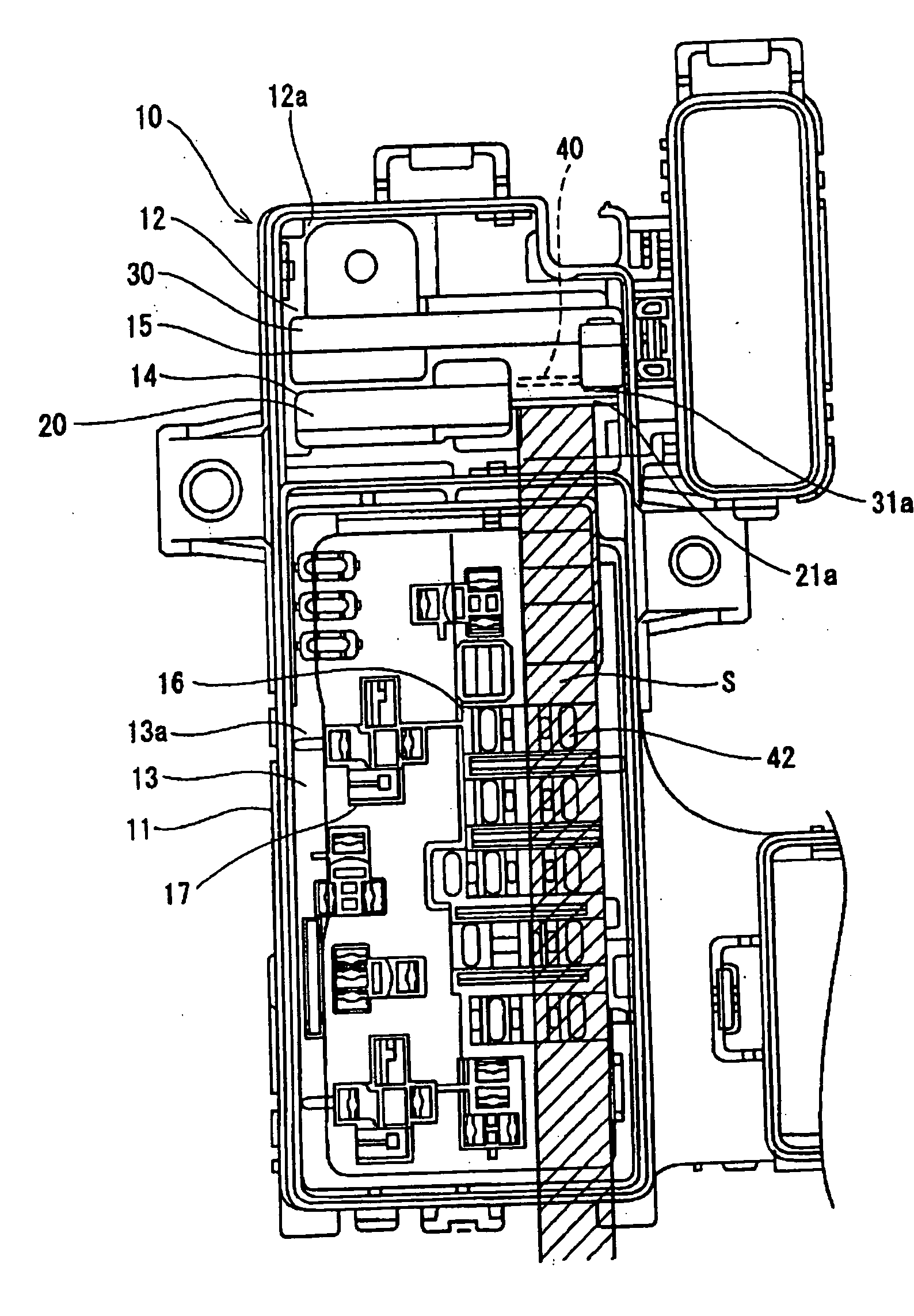
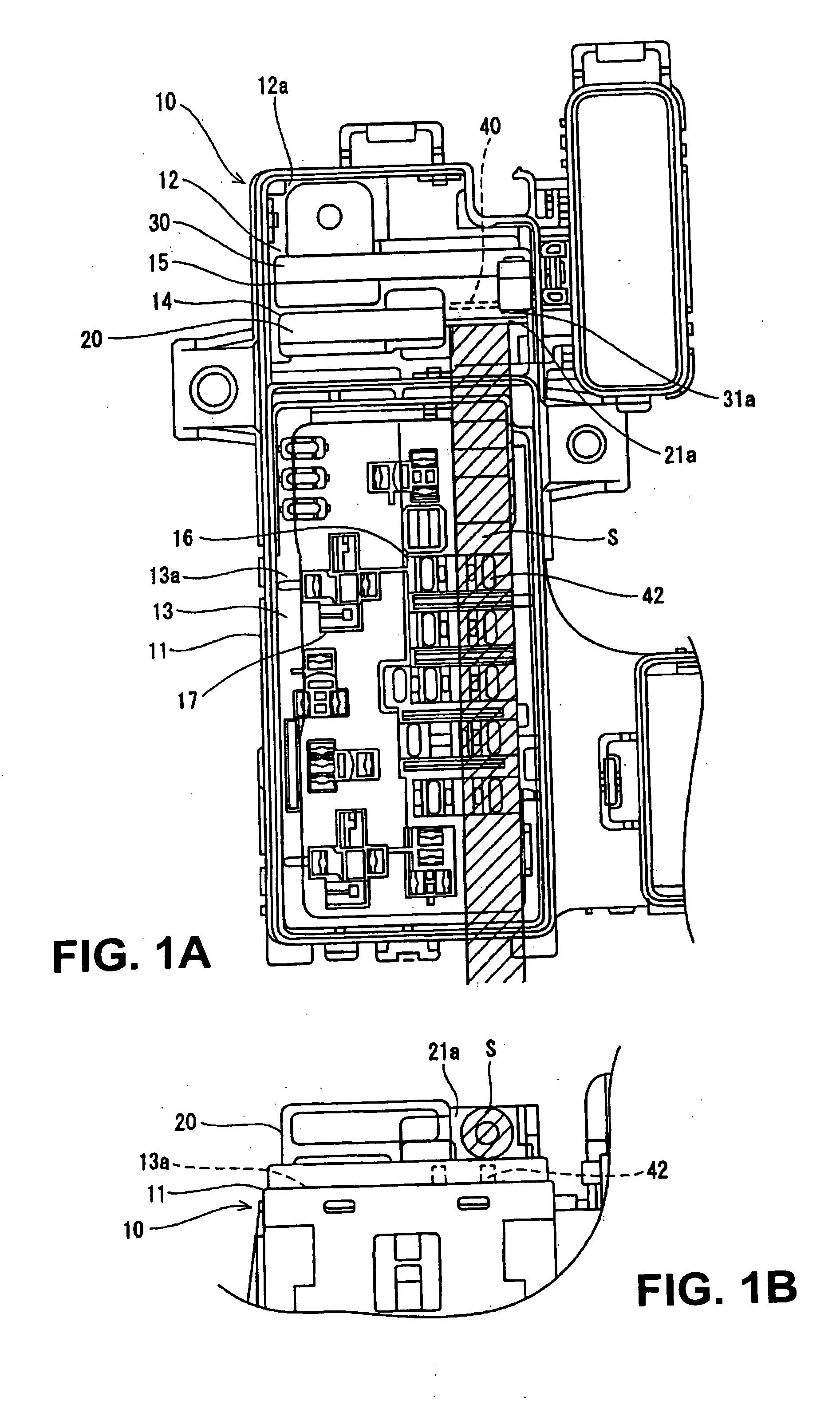
[0033] FIGS. 1 to 3 show an electrical junction box in accordance with various exemplary embodiments of the invention.

[0034] An electrical junction box 10 includes a body casing 11 comprising a first casing member 12 and a second casing member 13 (an upper cover is omitted in the drawings). The first and second casing members 12 and 13 are installed horizontally in the body casing 11. As shown in FIG. 1A, the first casing member 12 is provided on an upper surface 12a with a first fusible link containing-section 14 for accommodating a first integrated fusible link 20 (hereinafter referred to a “first fusible link”20) and with a second fusible link containing-section 15 for accommodating a second integrated fusible link 30 (hereinafter referred to a “second fusible link”30). On the other hand, the second casing member 13 is provided on an upper surface 13a with a plurality of fuse containing-sections 16 and a plurality of relay containing-sections 17.

[0035] The first fusible link con...

third embodiment

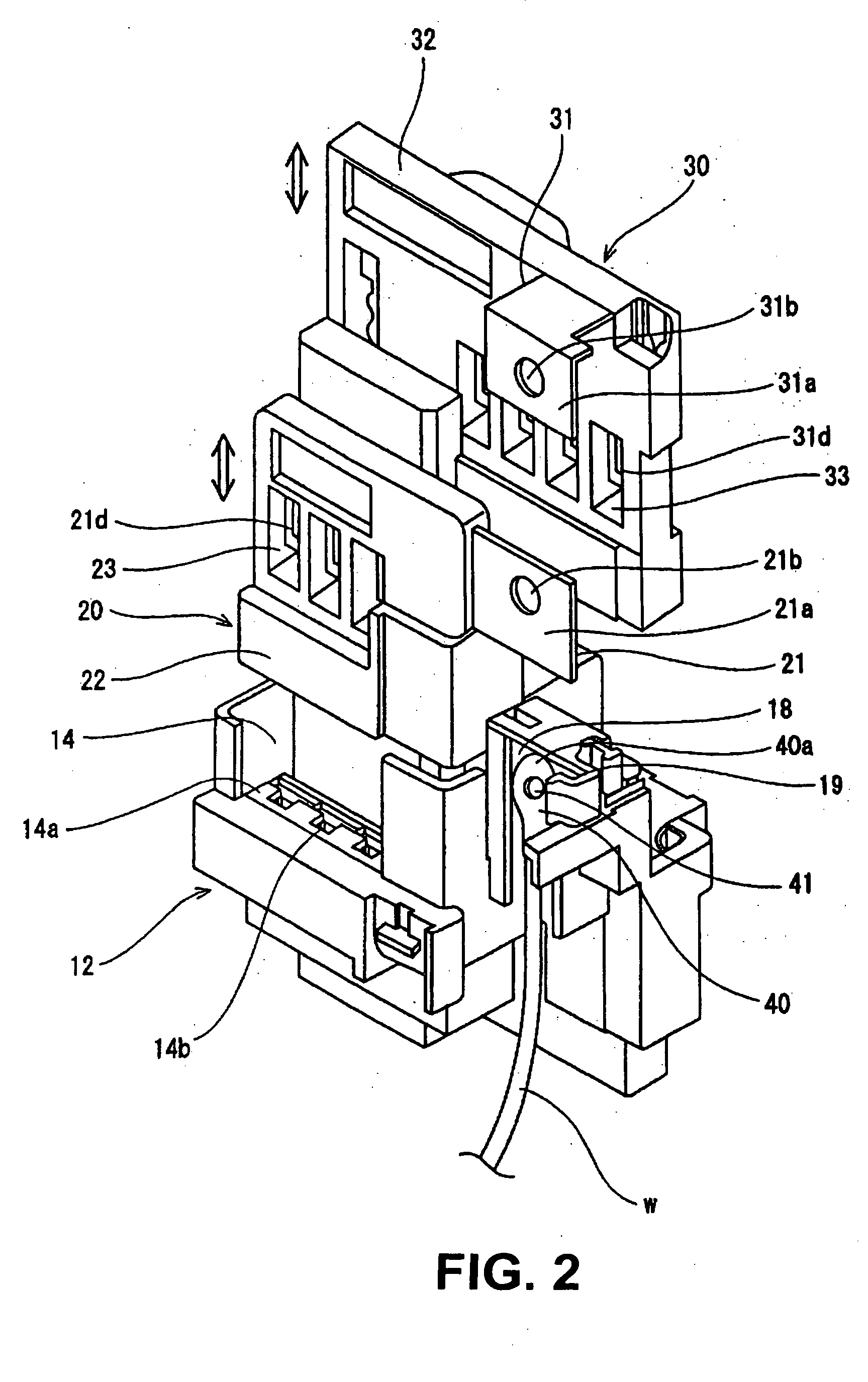
[0056] In a first fusible link 20′ in the third embodiment, an input terminal section 21a′ extends horizontally from a housing section 22′ at an upper surface side with a bolt fastening surface of the input terminal section 21a′ being directed upward. An intermediate bus bar 50 disposed in the electrical junction box is provided in upper and lower ends with bolt holes (not shown).

[0057] An upper end of the intermediate bus bar 50 is bent horizontally, is superposed on the input terminal section 21a′ of the first fusible link 20, and is fastened by a bolt. On the other hand, a bolt hole in a lower end of the intermediate bus bar 50 is aligned axially with the bolt hole in the press fitting terminal 40 and the bolt holes are fastened by a bolt.

[0058] According to the above structure, because the input terminal section 21a′ of the first fusible link 20′ projects horizontally along the upper surface of the body casing, it is possible to remove only the upper cover from the electrical j...


PUM


Abstract

In order to readily remove a fusible link fastened by a bolt from an electrical junction box, an electrical junction box includes a bus bar made of an electrical conductive metallic plate and that has an input terminal section, a plurality of output terminal sections, narrow fusible portions interposed between the input and output terminal sections. The junction box further includes a fusible link embedding the bus bar in molded resin integrally, a body casing containing the fusible link, and a press fitting terminal coupled to an end of an electrical power source cable. The press fitting terminal is connected to the input terminal section by a bolt. A bolt-joining portion between the input terminal section and the press terminal is disposed on a position higher than an upper surface of the body casing or a position opposite to an cutout provided in the body casing. A bolt-handling space for fastening or releasing a bolt is defined at a position opposite to the bolt-joining portion.

Description

CROSS-REFERENCE TO RELATED APPLICATION [0001] The invention claims priority to Japanese Patent Application No. JP 2003-403613 filed on Dec. 2, 2003. The disclosure of the prior application is incorporated herein by reference in its entirety. BACKGROUND OF THE INVENTION [0002] 1. Field of Invention [0003] This invention relates to an electrical junction box and more particularly relates to an electrical junction box in which an integrated FL (fusible link) includes a fusible link having a narrow fusible portion and an input terminal section provided on a bus bar, and the input terminal section is fastened on a terminal coupled to an end of an electrical power source cable by a bolt, thereby facilitating exchange of the fusible link and improving a service function. [0004] 2. Description of Related Art [0005] Heretofore, in an electrical junction box installed in a motor vehicle, a terminal of a fusible link is fastened to a terminal coupled to an end of an electrical cable by a bolt ...

Claims


Application Information

Patent Timeline
IPC IPC(8): H05K7/06H01H85/20H02G3/16
CPCH01H85/205H01H2085/208H01H2085/0555H01H85/0241
Inventor NOJIMA, SHIGERUMATSUMOTO, MANABUKATO, MITSUHIROSAITO, JUN
Owner SUMITOMO WIRING SYST LTD
Why Eureka
Try Eureka