Horizontally polarized omni-directional antenna

a dipole antenna and horizontal polarization technology, applied in the structural form of radiating elements, elongated active elements, resonance antennas, etc., can solve the problems of significant interference, inability to achieve maximum signal strength, and inability to meet broadband impedance, so as to improve broadband impedance match

Inactive Publication Date: 2005-06-02
FRC COMPONENT PROD
View PDF2 Cites 29 Cited by
  • Summary
  • Abstract
  • Description
  • Claims
  • Application Information

AI Technical Summary

Benefits of technology

[0009] It is a further object of the present invention to package the antenna elements in such a manner as to offer a high-degree of environmental reliability in a “swept-back” aerodynamic shape.
[0010] According to the invention, the foregoing and other objects are achieved in part by having a pair of bent dipoles patterned onto a circuit board that is positioned horizontally atop a dielectric shell. The dipoles are fed 180° out of phase by

Problems solved by technology

However, these newer, smaller antennas still commonly employ vertical polarization.
As the frequency spectrum becomes more crowded, these vertically polarized systems increasingly suffer from noise susceptibility, due in part to man-made noise that is in the vertical direction.
Likewise, multiple communications systems within the vertical polarized environment can cause significant interference.
However, maximum signal strength can only be achieved if all the ante

Method used


Image

  • Horizontally polarized omni-directional antenna
  • Horizontally polarized omni-directional antenna
  • Horizontally polarized omni-directional antenna

Examples


Embodiment Construction

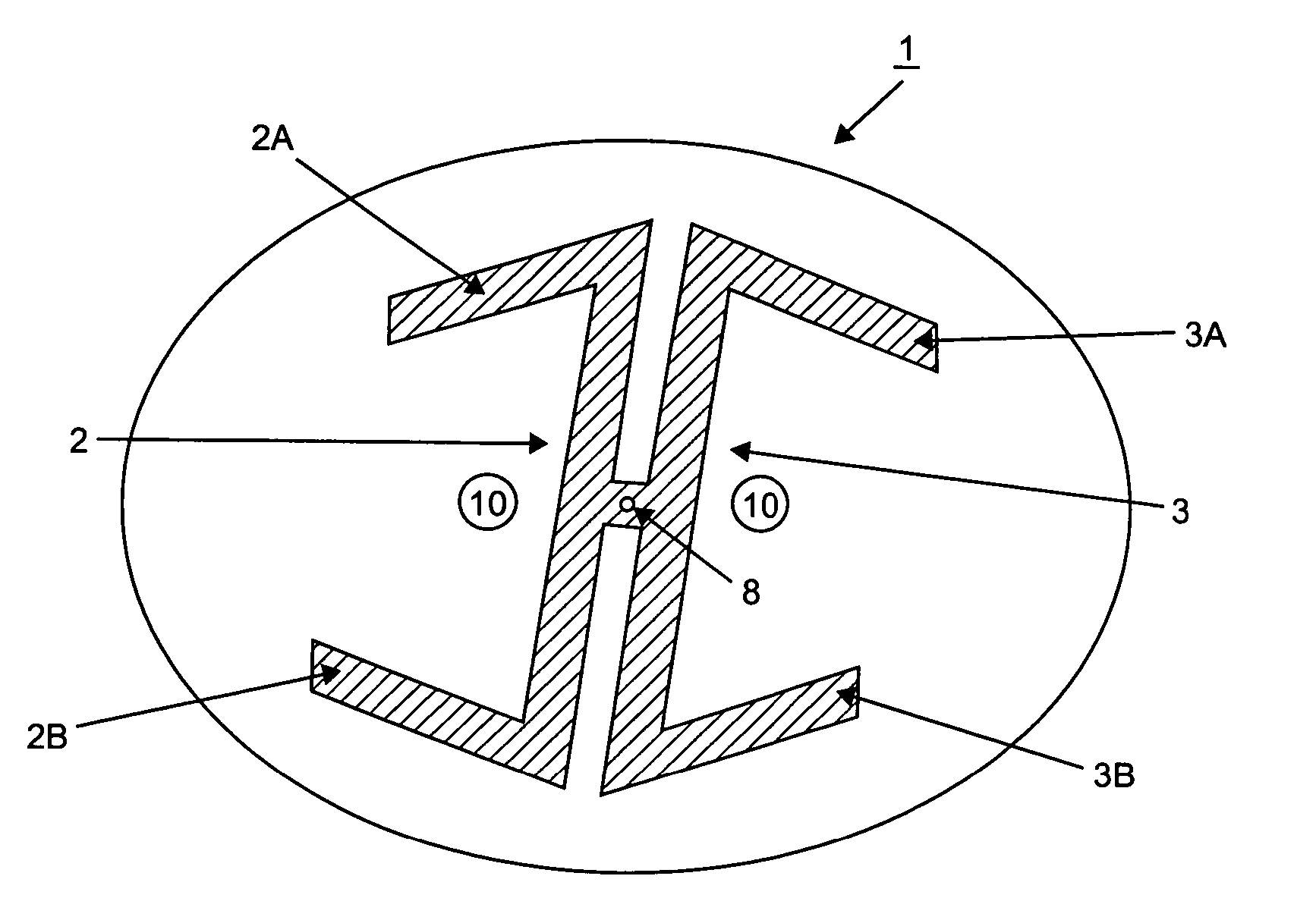
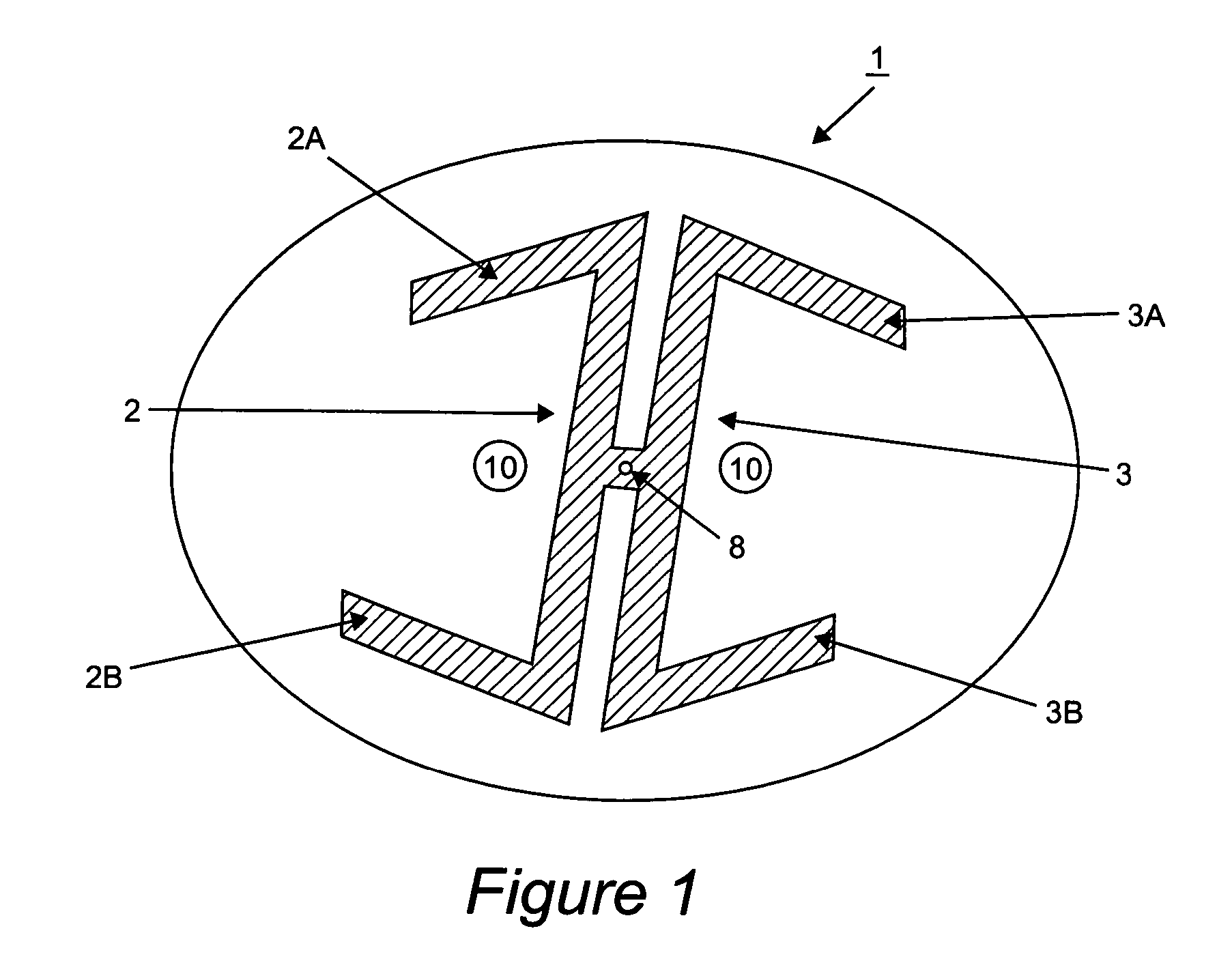
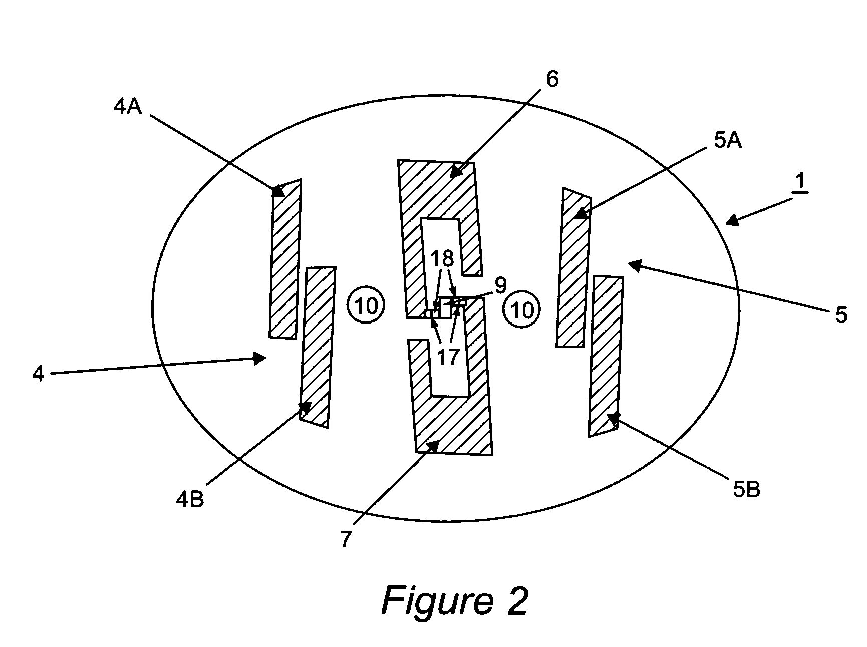
[0021] Referring now to the drawings, FIGS. 1 and 2 show the dipole elements and feed network patterned onto a circuit board. The board consists of a dielectric substrate that is plated on both sides with a metalization. In an example of this embodiment, the board is {fraction (1 / 16)}″ thick FR4 plated with 1 oz copper on both the top and bottom. FIG. 1 shows the metalization that is patterned onto the bottom of the circuit board 1, while FIG. 2 shows the metalization that is patterned onto the top of the circuit board 1. It should be understood that the metalization can be using other materials such as silver, tin, metal alloys, etc. and not be limited to copper.

[0022]FIG. 1 shows dipole elements 2 and 3 that are formed on the bottom of the circuit board 1. Elements 2 and 3 comprise the initial bent form of the dipole. Dipole element 2 has bent subelements 2A and 2B while dipole element 3 has bent subelements 3A and 3B. Dipole elements 2 and 3 are mirror images of each other and a...


PUM


Abstract

An antenna apparatus comprising bent dipoles and fed by a quarter-wave balun transformer with a single coaxial cable feed is disclosed. In this embodiment, the antenna elements are patterned onto a dielectric circuit board which is then mounted horizontally into a molded shell. The antenna is tuned by trimming the bent dipoles patterned on the circuit board.

Description

BACKGROUND OF THE INVENTION [0001] 1. Field of the Invention [0002] The present invention generally relates to a pair of bent dipole antennas fed with a single coaxial cable used to provide horizontally polarized, omni-directional coverage with a minimum amount of vertical cross-polarization for wireless communications. [0003] 2. Background Description [0004] Antennas providing omni-directional coverage with a desired overhead “null’ are typically vertical polarized “whip” antennas. Whip antennas are suitable for ground based fixed structures such as antenna towers. The mobile environment has necessitated the development of smaller more integrated antenna. Printed circuit board dipole antennas have been developed to meet this need. However, these newer, smaller antennas still commonly employ vertical polarization. As the frequency spectrum becomes more crowded, these vertically polarized systems increasingly suffer from noise susceptibility, due in part to man-made noise that is in ...

Claims


Application Information

Patent Timeline
IPC IPC(8): H01Q1/24H01Q1/38H01Q9/36
CPCH01Q1/242H01Q9/36H01Q1/38
Inventor EL-MAHDAWY, AHMEDHESTNESS, MARK
Owner FRC COMPONENT PROD
Why Eureka
Try Eureka