Orthopedic and dental implant system and method

a technology of dental implants and implants, applied in the field of orthopaedic and dental implants, can solve the problems of cementing and resolidifying on the same, and achieve the effect of reducing the number of implants

a technology of dental implants and implants, applied in the field of orthopaedic and dental implants, can solve the problems of cementing and resolidifying on the same, and achieve the effect of reducing the number of implants

US20050119666A1Active Publication Date: 2005-06-02BUBB STEPHEN K

Image

  • Orthopedic and dental implant system and method
  • Orthopedic and dental implant system and method
  • Orthopedic and dental implant system and method

Examples


Embodiment Construction

I. Introduction and Environment

[0026] As required, detailed embodiments of the present invention are disclosed herein; however, it is to be understood that the disclosed embodiments are merely exemplary of the invention, which may be embodied in various forms. Therefore, specific structural and functional details disclosed herein are not to be interpreted as limiting, but merely as a basis for the claims and as a representative basis for teaching one skilled in the art to variously employ the present invention in virtually any appropriately detailed structure.

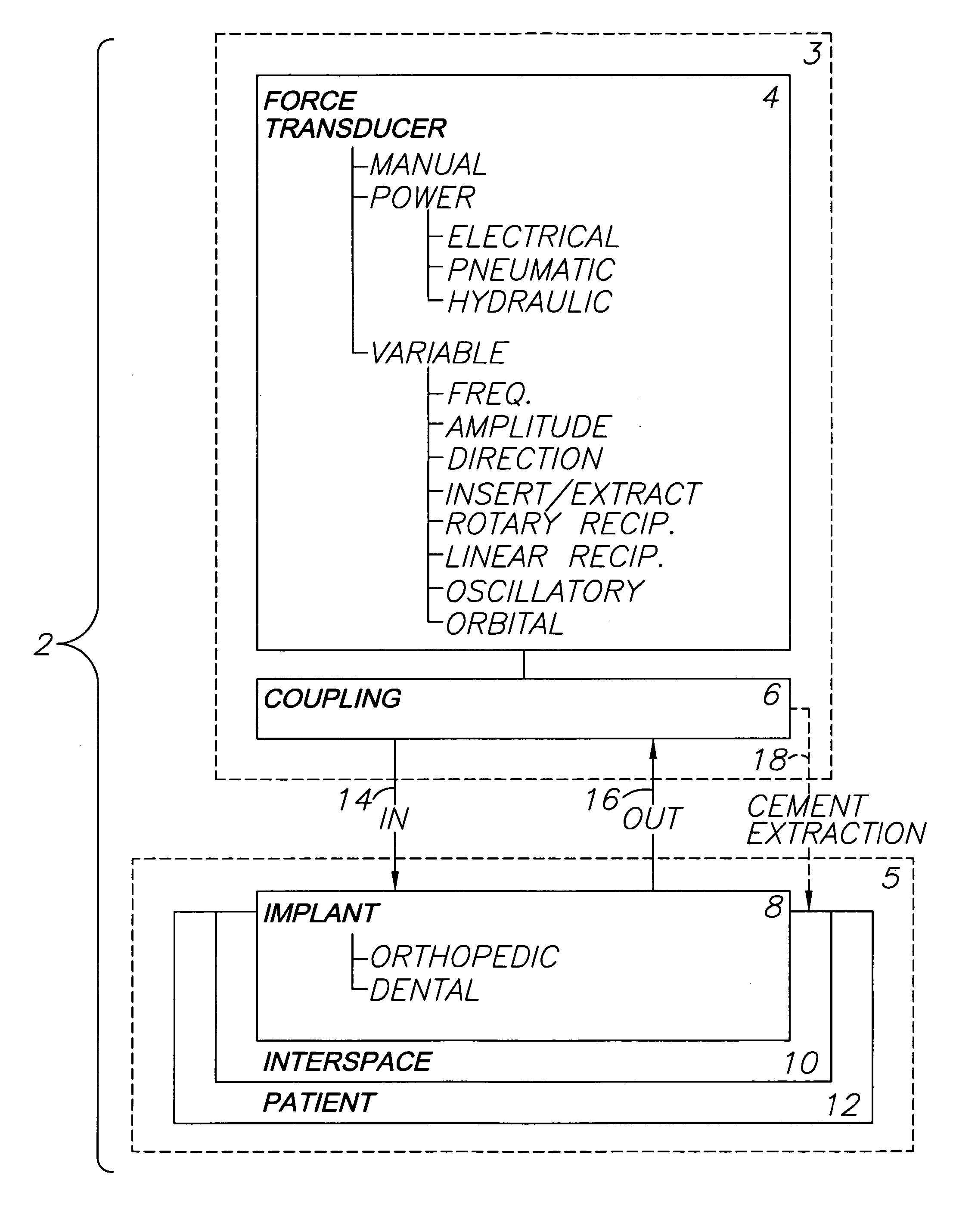
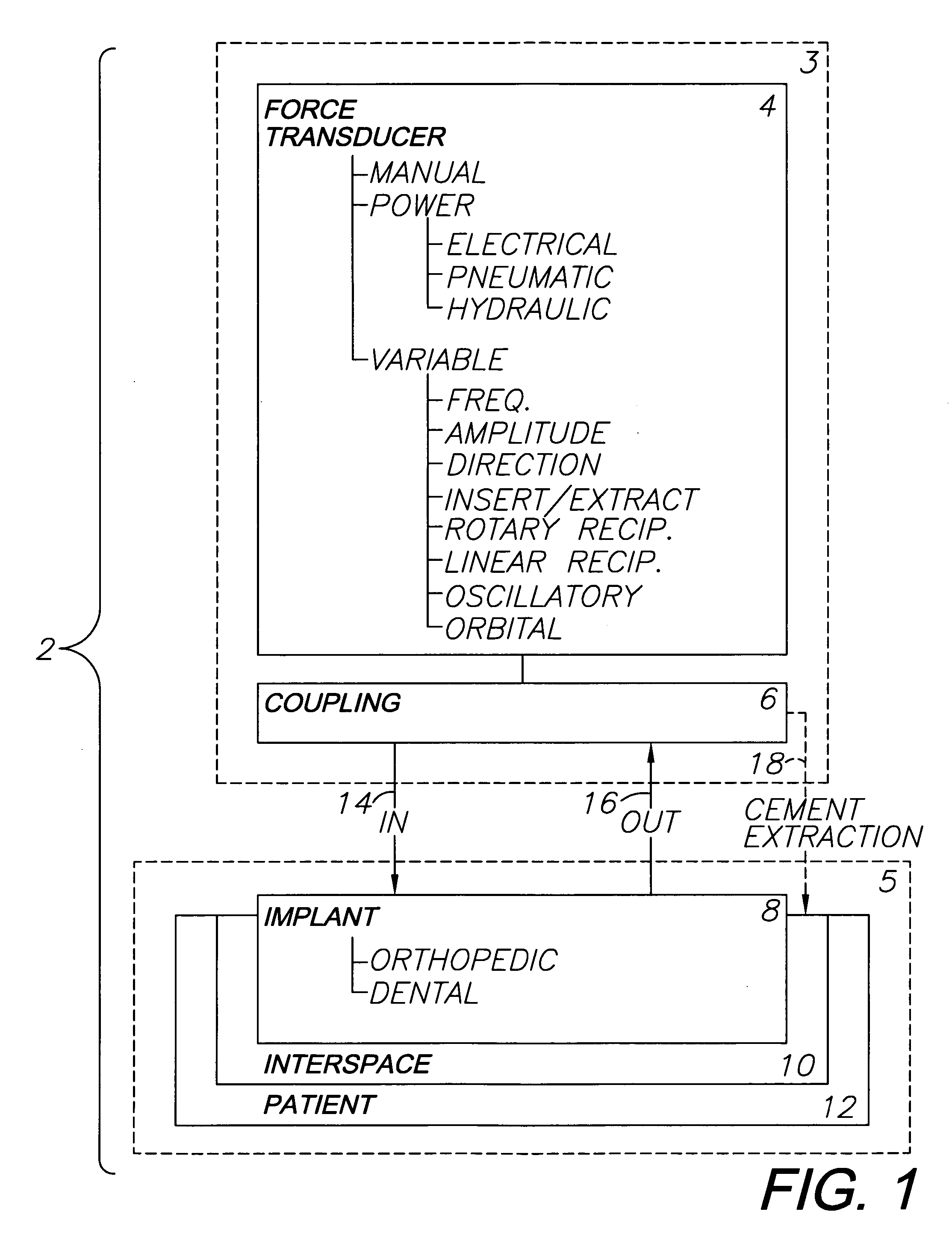
[0027] Referring to FIG. 1, the reference numeral 2 generally designates an orthopedic and dental implant system embodying an aspect of the present invention. The system 2 generally includes an external subsystem 3 including a force transducer 4, which can comprise a manual device, such as a slaphammer, or an electrical, pneumatic or hydraulic power device. The transducer 4 is adapted for variable operation, including such var...


PUM


Abstract

A system for removing osteal cement and prosthetic joint components in connection with a prosthetic joint revision includes a controller connected to and controlling operation of a transducer, such as a surgical saw or drill. A tool mounted on the transducer is adapted for engaging the prosthetic joint cement mantel and melting an engagement portion of same. The cement in the engagement portion is resolidified with the tool tip embedded therein. The tool thus bonds to the cement mantel, and is used for vibrating, softening and breaking up same when operation of the transducer resumes. An osteal cement and prosthetic device removal method includes the steps of melting an engagement portion of the osteal cement mantel, bonding a transducer-mounted tool to the cement mantel by resolidifying the cement engagement portion and reactivating the transducer for vibrating, softening and breaking up the cement mantel whereby it can be removed from the patient.

Description

BACKGROUND OF THE INVENTION [0001] 1. Field of the Invention [0002] The present invention relates generally to implant systems and methods for orthopedic and dental applications. More specifically, the present invention relates to implant insertion and extraction with couplings for attachment to manual and power force transducers with control over force variables. [0003] 2. Description of the Related Art [0004] Many orthopedic procedures involve implants for replacing damaged and dysfunctional joints. For example, total joint replacement (TJR) and hemi arthroplasty (replacing one-half of the joint) procedures have been developed. Hips, knees, elbows, shoulders and wrists are commonly reconstructed with implants, such as prosthetic joints that are designed for optimal wear, comfort, biocompatibility and performance. Such replacement joint implants have benefited many patients by restoring their mobility and other functions. [0005] Reconstructive dental procedures include installing i...

Claims


Application Information

Patent Timeline
02 Jun 2005
Publication
US20050119666A1
IPC
A61B17/32; A61C8/00; A61F2/00; A61F2/30; A61F2/36; A61F2/46
CPC
A61B17/320068; A61F2002/4628; A61B17/8847; A61C8/0089; A61F2/30771; A61F2/36; A61F2/367; A61F2/4607
Inventors
BUBB, STEPHEN K.