Kneepad having a sling strap system

a kneepad and sling strap technology, applied in the field of kneepads having sling strap systems, can solve the problems of limiting the life of the kneepad, a number of deficiencies in the traditional protective kneepad, and achieving the effect of convenient adjustmen

Inactive Publication Date: 2005-06-09
BLACK & DECKER INC
View PDF53 Cites 12 Cited by
  • Summary
  • Abstract
  • Description
  • Claims
  • Application Information

AI Technical Summary

Benefits of technology

[0004] It is therefore desirable to have a strap assembly for a protective kneepad that can be easily adjusted to surround a number of different sized knees and legs for various users, and provides a way to replace a portion of the strap assembly should it become worn or break. The present invention is directed at correcting these deficiencies in the prior art.
[0005] In one aspect of the invention, a kneepad includes a base, a first and second mounting ring attached to the base, and an elongated strap removably attached to the first and second mounting rings. During use, the base is placed over a knee of user. The elongated strap is placed behind the knee of the user and a first end of the elongated strap is wrapped around the knee and inserted into the first mounting ring. A second end of the elongated strap is then wrapped around the knee and inserted into the second mounting ring. The first and second ends of the elongated strap are pulled through the first and second mounting rings to obtain a desired tension between the kneepad and the knee. Once the desired tension is obtained, the kneepad is secured to the knee.

Problems solved by technology

These traditional protective kneepads, however, suffer from a number of deficiencies.
This design limits the life of the kneepad due to the fact the entire kneepad must be replaced once a portion of the strap assembly becomes worn or breaks.
Additionally, this design creates problems in that a designer must design a strap assembly for the protective kneepad that can comfortably surround a number of different sized knees and legs for various users.

Method used


Image

  • Kneepad having a sling strap system
  • Kneepad having a sling strap system
  • Kneepad having a sling strap system

Examples


first embodiment

[0024] In the elongated strap 128 shown in FIGS. 6A-B, the free ends 118, 122 of the straps 112 includes a surface of minute hooks 133 while the padded area 120 of the elongated strap 128 and a portion of the first and second straps 112 includes a first and second attachment area 136, 138 having surfaces of uncut pile. The elongated strap 128 is designed such that when the free ends 118, 122 of the straps 112 are folded back against the padded area 120, the surface of minute hooks 133 will engage the surfaces of uncut pile 136, 138, thereby securing the free end of one of the straps 112 against the padded area 120 and securing the free end of the other strap 112 against the padded area 120.

[0025] In a second embodiment of the elongated strap 128′ shown in FIG. 6C, a free end 118′ of one strap 112′A and a free end 122′ of the other strap 112′B make up a hook and loop fastening system, but any fastening system could be used. In the second embodiment, the free end 118′ of one of the st...

second embodiment

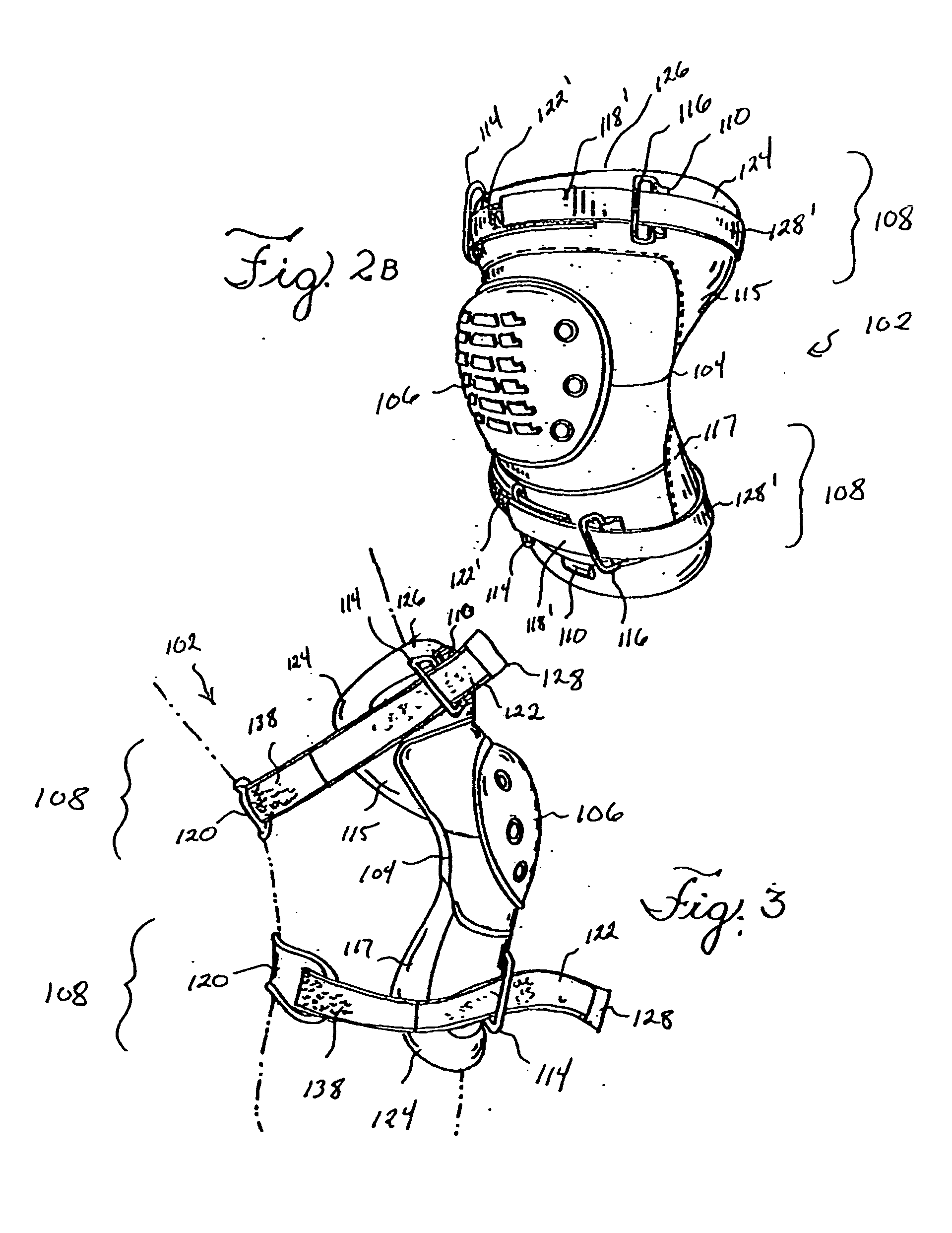
[0031] In a second embodiment shown in FIGS. 2B and 4B, once the desired tension is achieved between the kneepad 102 and the knee of the user, the free ends 118′, 122′ of the straps 112′A, 112′B are secured to each other in front of the kneepad 102, thereby securing one end of the kneepad 102 to the knee of the user.

[0032] In other embodiments, in alternative to the mounting rings 114, 116, other mounting device / systems may be provided on the flexible base 104 and / or the elongated strap 128, 128′ such as hook and loop fastening systems, snaps, fabric loops, buckles, or other means. For example, in embodiments using a snap, the free ends of the elongated strap could make up a snap fastener; a free end of the strap and a mounting area of the flexible base could make up a snap fastener; or a free end of a strap and a first attachment area of an elongated strap could make up a snap fastener. Similarly, in embodiments using a buckle, the free ends of the strap could make up a buckle; a f...


PUM


Abstract

A kneepad includes a base, a first and second mounting ring attached to the base, and an elongated strap removably attached to the first and second mounting rings. During use, the base is placed over a knee of user. The elongated strap is placed behind the knee of the user and a first end of the elongated strap is wrapped around the knee and inserted into the first mounting ring. A second end of the elongated strap is then wrapped around the knee and inserted into the second mounting ring. The first and second ends of the elongated strap are pulled through the first and second mounting rings to obtain a desired tension between the kneepad and the knee. Once the desired tension is obtained, the kneepad is secured to the knee.

Description

RELATED APPLICATIONS [0001] The present patent document claims the benefit of the filing date under 35 U.S.C. §119(e) of Provisional U.S. Patent Application Ser. No. 60 / 527,851, filed Dec. 8, 2003, the entire contents of which is hereby incorporated by reference.BACKGROUND [0002] Historically, to prevent knee injuries during physical activity that requires being in a kneeling position, a user would wear a protective kneepad over the front of their knee. Traditional protective kneepads normally include some type of rigid cap secured against the front of a knee by some type of strap that surrounds the knee and leg of the user. [0003] These traditional protective kneepads, however, suffer from a number of deficiencies. For example, traditional kneepads are often designed to have a strap assembly that is permanently fixed to the protective kneepad. This design limits the life of the kneepad due to the fact the entire kneepad must be replaced once a portion of the strap assembly becomes ...

Claims


Application Information

Patent Timeline
Patent Type & Authority Applications(United States)
IPC IPC(8): A41D13/06
CPCA41D13/065A41D13/0568
Inventor CUNNINGHAM, IAN W.
Owner BLACK & DECKER INC
Why Eureka
Try Eureka