Pneumatically powered lift ambulance cot

a pneumatically powered, cot technology, applied in the field of ambulance cots, can solve the problems of increasing the risk of attendants obtaining back injuries or exacerbating existing ones

Active Publication Date: 2005-06-09
FERNO WASHINGTON
View PDF15 Cites 41 Cited by
  • Summary
  • Abstract
  • Description
  • Claims
  • Application Information

AI Technical Summary

Problems solved by technology

Unfortunately, lifting or raising a loaded ambulance cot from this low height increases the risk to these attendants obtaining a back injury or exacerbating an existing one.

Method used


Image

  • Pneumatically powered lift ambulance cot
  • Pneumatically powered lift ambulance cot
  • Pneumatically powered lift ambulance cot

Examples


Embodiment Construction

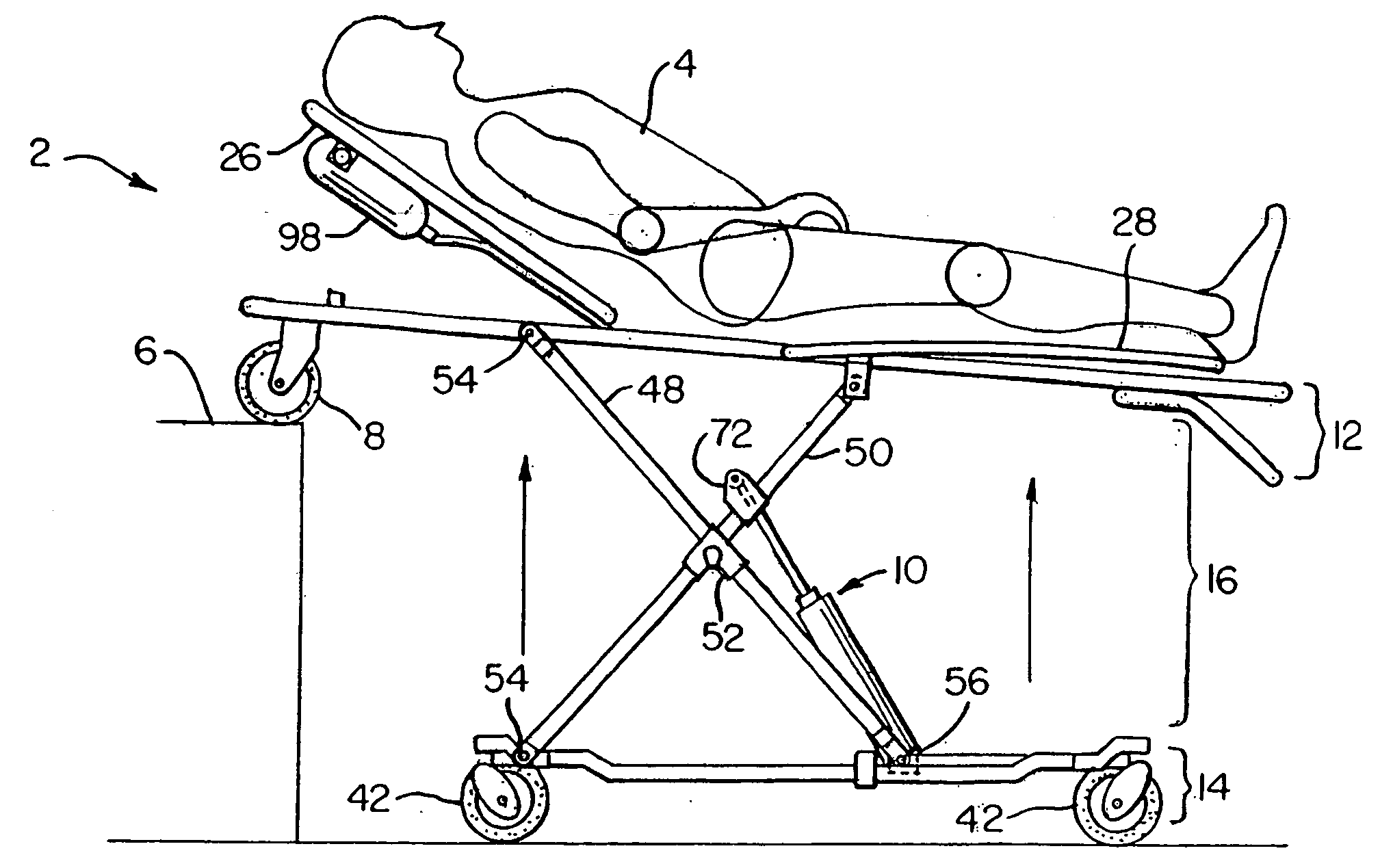
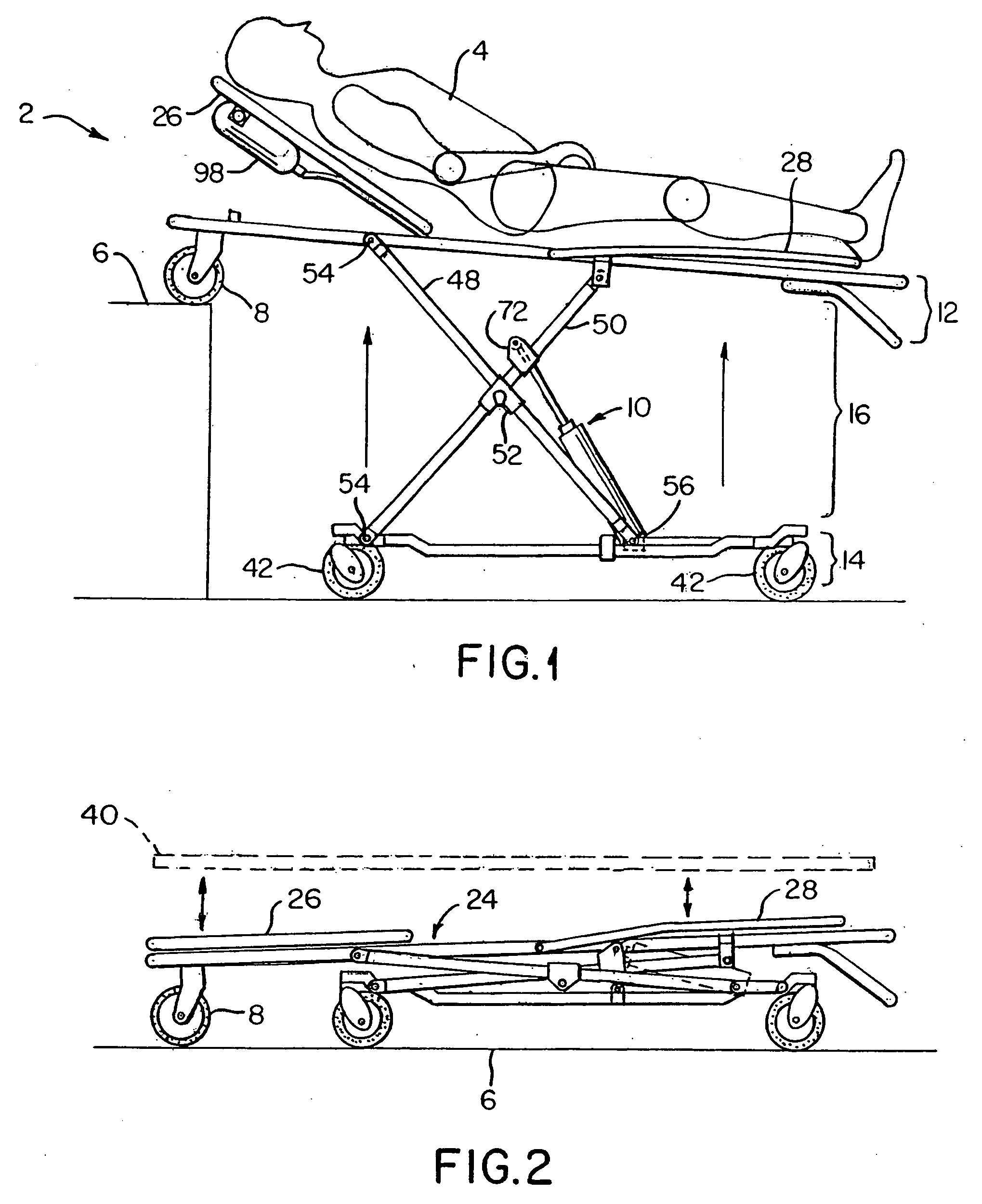
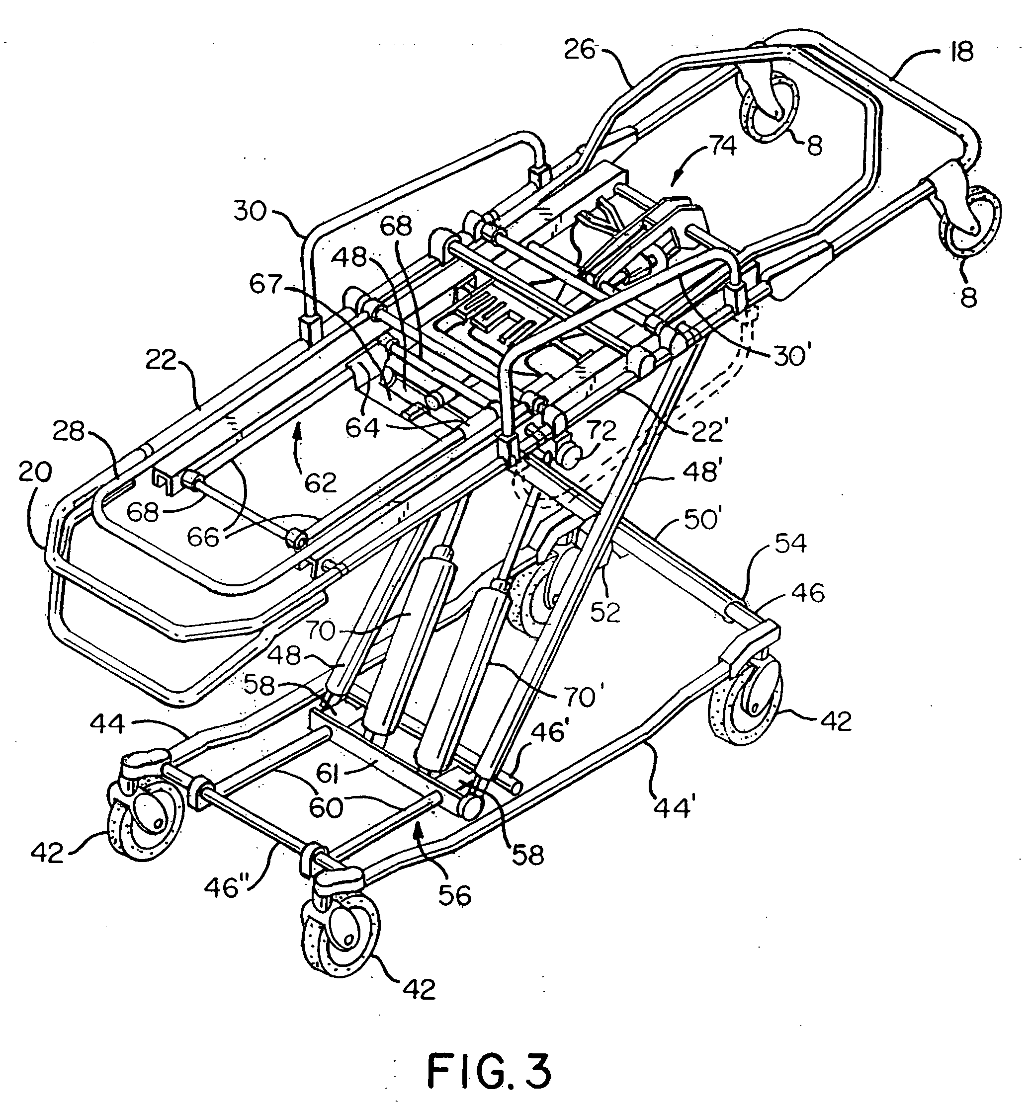
[0016] With reference to FIGS. 1-3, a retractable ambulance cot according to one embodiment of this invention is shown generally as 2. Upon the cot 2 a patient 4 may be supported, and conveniently loaded onto an elevated surface 6, such as for example, the transport bay of an ambulance. Referring to FIG. 1, the cot 2 is illustrated in an elevated position. It is to be appreciated that a single attendant can hold and manipulate the trailing end of the cot 2 in the elevated position in order to rest loading wheels 8 provided at the leading end of the cot onto the elevated surface 6. Operation of an associated pneumatic lift mechanism shown generally as 10 of the cot 2 as described herein in a later section, causes the undercarriage to be pneumatically raised to the level of the elevated surface 6 allowing the attendant to transfer the cot 2 thereon in the lowered position as depicted by FIG. 2. The pneumatic lift mechanism 10 also pneumatically raises the cot 2 from the lowered positi...


PUM


Abstract

A collapsible pneumatically operated ambulance cot having a support frame, a wheeled base, a support mechanism disposed therebetween, and a lift mechanism for pneumatically moving the upper frame relative to the lower frame is disclosed. The lift mechanism permits a single attendant to raise the cot from a lowered position to a raised position, and an infinite number of positions therebetween, and to raise the wheeled base relative to the support frame to situate the cot onto an elevated surface such as the transport deck of an ambulance.

Description

CROSS-REFERENCE TO RELATED APPLICATIONS [0001] This application claims the benefit of U.S. Provisional Application Ser. No. 60 / 517,582, filed Nov. 5, 2003.FIELD OF THE INVENTION [0002] This invention relates to ambulance cots and more particularly to ambulance cots having pneumatically, operated collapsible frame structures to facilitate manual operation by a single operator from the ground into an ambulance. BACKGROUND OF THE INVENTION [0003] In order to situate a conventional non-powered ambulance cot into the back of an ambulance, two or more attendants often must lift the cot from a relatively low height of approximately 15 cm from the ground to a height of almost 1 meter. Unfortunately, lifting or raising a loaded ambulance cot from this low height increases the risk to these attendants obtaining a back injury or exacerbating an existing one. Accordingly, providing a power lift ambulance cot for emergency medical services and ambulance-related services that reduces the physical...

Claims


Application Information

Patent Timeline
Patent Type & Authority Applications(United States)
IPC IPC(8): A61G1/02A61G1/056A61G7/012
CPCA61G1/0567A61G7/012A61G1/0293A61G1/0262A61G1/0212A61G1/0237
Inventor BENEDICT, WILLIAM H.CHINN, ROBERT C.SUTTON, WARREN D. SR.
Owner FERNO WASHINGTON
Why Eureka
Try Eureka