Modular workbench

Inactive Publication Date: 2005-02-24
CASE CORPORATION
View PDF10 Cites 39 Cited by
  • Summary
  • Abstract
  • Description
  • Claims
  • Application Information

AI Technical Summary

Benefits of technology

[0015] This invention provides a simple-to-install upper shelf assembly that is fully adjustable in height. Permanent spacer are installed on the shelf vertical member in combination with long shoulder rivets resulting in a gap at installation between the leg vertical member and the shelf vertical member whereby the lower shelf horizontal members can be assembled and disassembled without the need to remove the shelf vertical member.
[0016] The upper shelf vertical member of U-shaped cross section with a pair of outward protruding flanges, provides two adjacent lateral surfaces to permit the fastening of an upper shelf horizontal member at varying heights, and provides two outward facing flanged surfaces so that length-wise members can be installed using the same interlocking fastening scheme which prevents the members from becoming loose under a vibration environment.
[0017] This inventi

Problems solved by technology

Prior art modular workbenches do not permit continual lengthwise expansion of the workbench primary working surface and do not permit continual lengthwise expansion of the upper shelf holding surface.
Workbench patents prior to this 1924 date could not have considered designing their leg assemblies and upper shelf brackets components to incorporate a butt joint to accommodate a specified quantity of same width dimensional lumber pieces since

Method used


Image

  • Modular workbench
  • Modular workbench
  • Modular workbench

Examples


Embodiment Construction

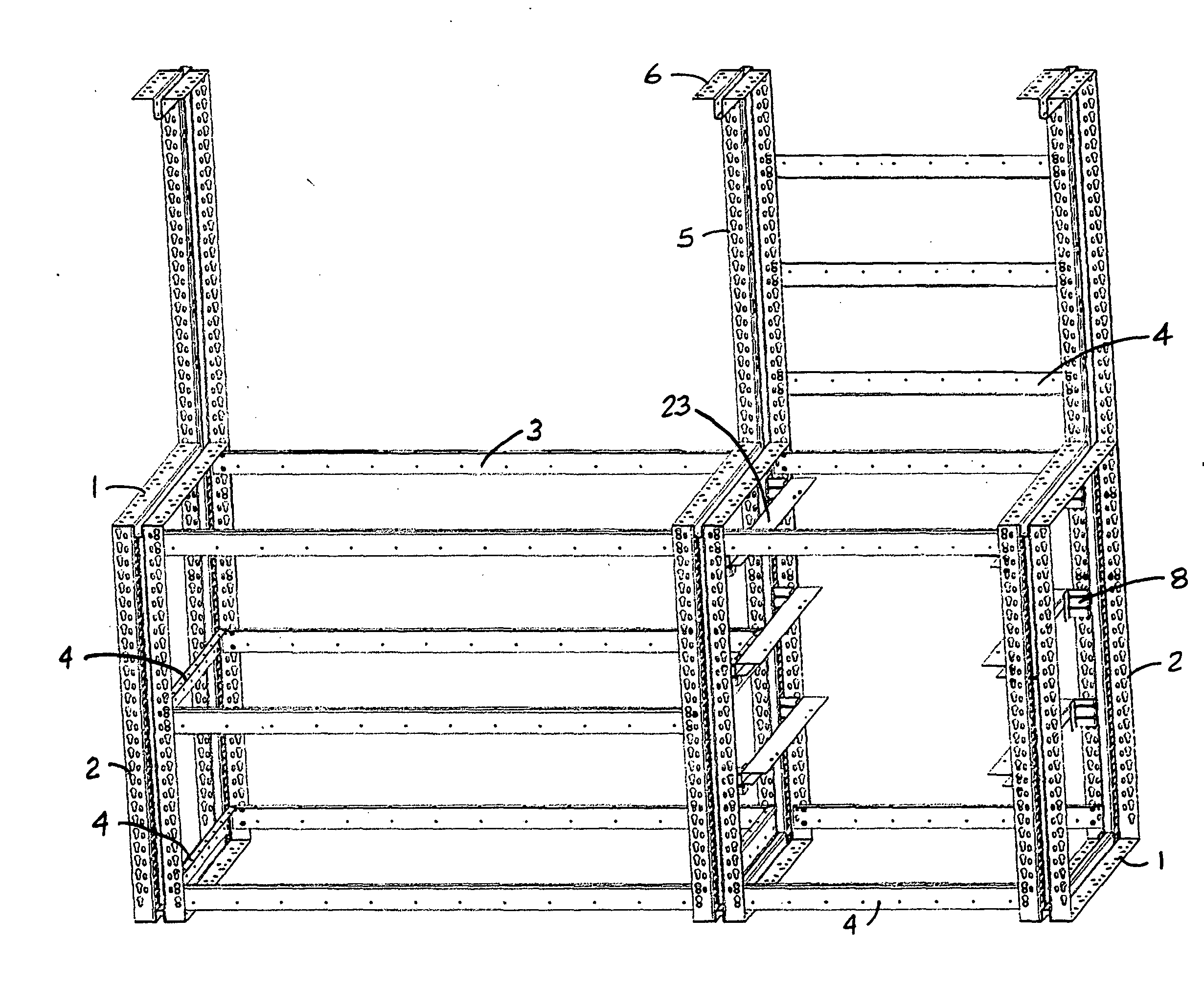
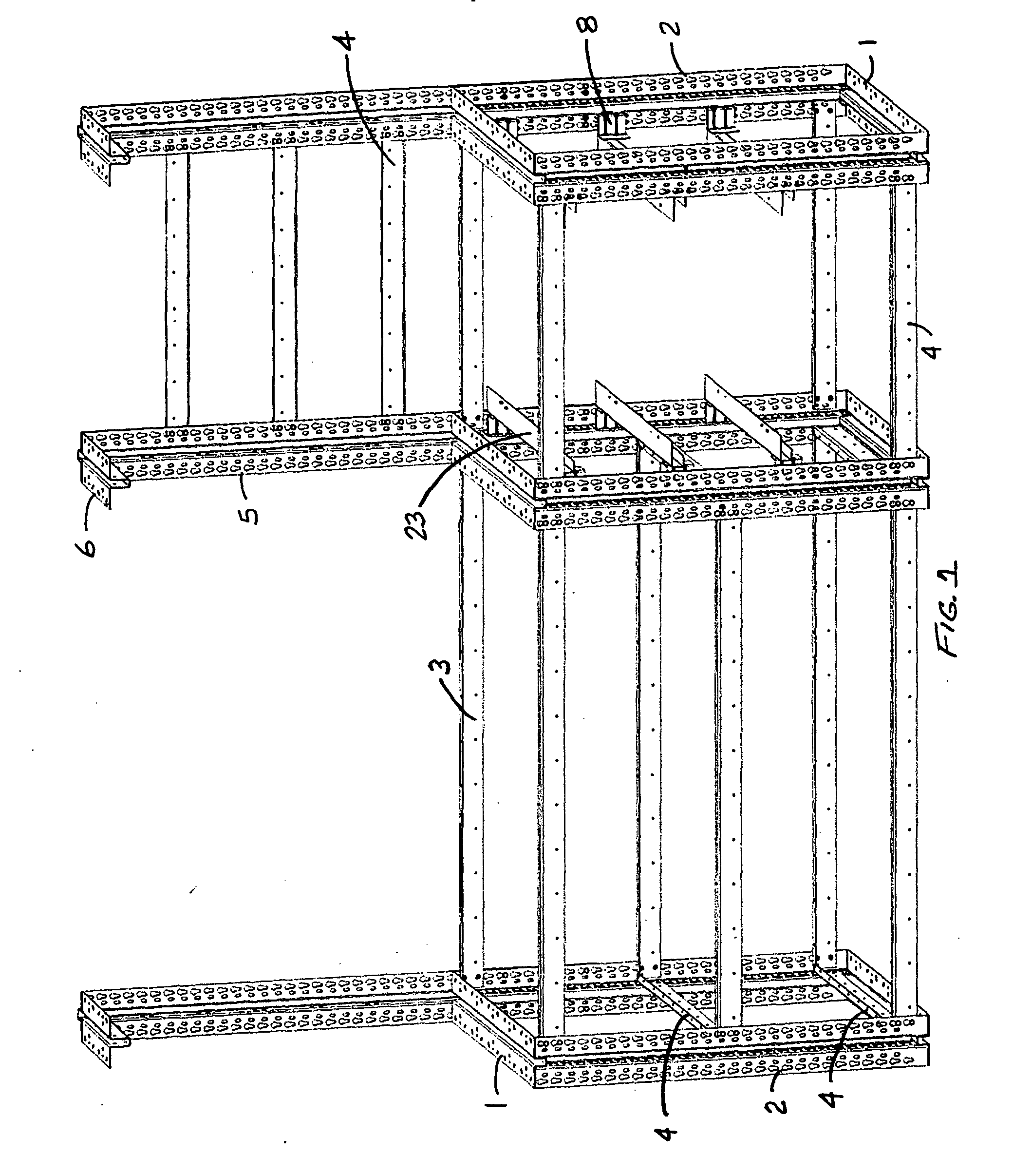
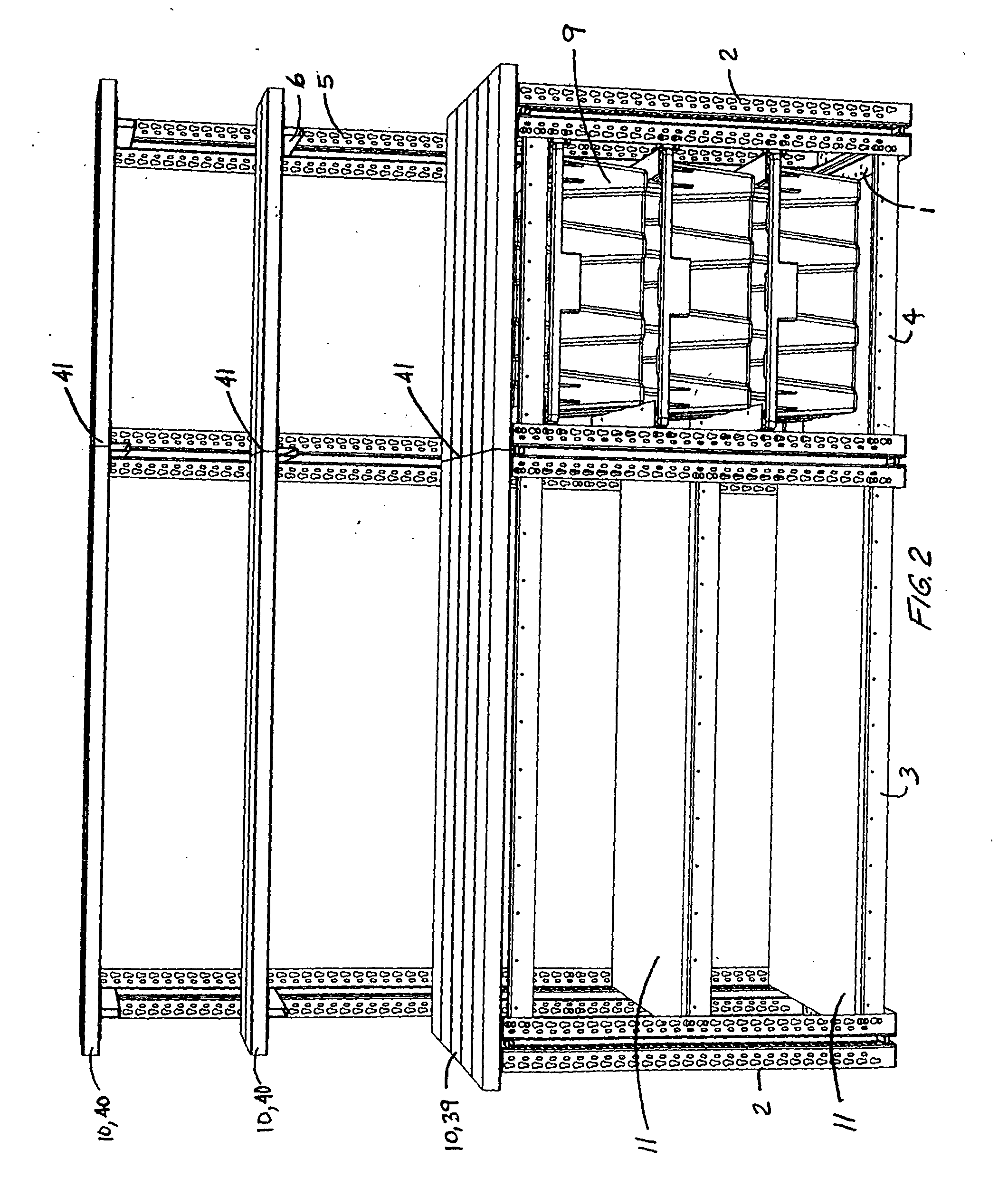
[0048] A modular workbench assembly is presented that provides the user with an infinite number of potential workbench configurations ranging from a simple two legged workbench for a user with limited space, to a continuous workbench system comprising of a continuous primary working surface and a continuous upper shelf storage surface with a large quantity of legs for spanning the length of a large production facility. An infinite number of potential workbench configurations is possible with varying quantity of lower shelf sets, drawer sets and upper shelf sets.

[0049] This invention allows continual workbench lengthwise expansion by featuring a unique leg assembly and a unique upper shelf assembly both of which utilize nested members of U-shaped cross section with pairs of outward protruding flanges, and are fastened at their interface. Localized cutouts are incorporated into the leg vertical member to enable nesting with the leg horizontal member. Likewise, localized cutouts are i...


PUM


Abstract

A modular workbench assembly is presented that provides the user with an infinite number of potential workbench configurations with varying quantities of lower shelf sets, drawer sets, and upper shelf sets. This invention allows economical continual workbench lengthwise expansion by featuring a unique leg assembly and a unique upper shelf assembly that permit a specified number of dimensional lumber pieces to span and fasten to its top surface, or allows the fastening of twice as many dimensional lumber pieces forming a butt joint at the central vertical axis of both the leg assembly and the upper shelf assembly. The leg vertical member of U-shaped cross section features a pair of outward and opposite lengthwise protruding flanges and features a pair of adjacent lateral mounting surfaces so that lateral members, lengthwise members and upward members can be installed simultaneously using a unique, common interlocking fastening scheme which prevents the members from becoming loose under a vibration environment. A unique upper shelf assembly is presented that snaps into place on a leg assembly and is fully adjustable. The upper shelf assembly permits installation of additional structural members onto the leg assembly without removal of the upper shelf assembly from the leg assembly. A universal drawer rail assembly is presented that enables quick and sturdy assembly that is fully interchangeable as either a left drawer rail or a right drawer rail.

Description

CROSS-REFERENCE TO RELATED APPLICATIONS [0001] Reference U.S. patent application Ser. No. 09 / 775,753 entitled Workbench filed pro se Feb. 5, 2001. Referenced patent addresses the leg's ability to accept a specified quantity of dimensional lumber pieces spanning its top surface or accepts the fastening of twice as many dimensional lumber pieces forming a butt joint at the central vertical axis of the leg assembly.FEDERAL SPONSORED RESEARCH OR DEVELOPMENT [0002] This invention is not related in any means to any federal sponsored research or development. BACKGROUND OF THE INVENTION [0003] A modular workbench assembly is presented that provides the user with an infinite number of potential workbench configurations with varying quantities of lower shelf sets, drawer sets, and upper shelf sets. [0004] Prior art modular workbenches do not permit continual lengthwise expansion of the workbench primary working surface and do not permit continual lengthwise expansion of the upper shelf holdin...

Claims


Application Information

Patent Timeline
IPC IPC(8): A47B57/50A47B96/14B25H1/02F16B12/30
CPCA47B57/50F16B12/30B25H1/02A47B96/1475
Inventor SHEAHAN, KEVIN PATRICKBULK, THOMAS ALAN
Owner CASE CORPORATION
Why Eureka
Try Eureka