Electromotive drives

a technology of electromechanical or electromotive drives, applied in the direction of electric generator control, vehicle sub-unit features, gearing, etc., can solve the problems of difficult shifting of the rotational axis of each of the traction rollers, the success of traditional solutions is limited, and the use of iris plates can be very complicated

Active Publication Date: 2008-06-19
FALLBROOK INTPROP COMPANY
View PDF37 Cites 40 Cited by
  • Summary
  • Abstract
  • Description
  • Claims
  • Application Information

AI Technical Summary

Benefits of technology

[0016]In another embodiment, a continuously variable transmission is disclosed that is integrated with an electric motor, the stator of the electric motor attached to a rotating shaft which transfers power to the idler, and the rotor of the electric motor attached to the input disc. The stator and rotor of the electric motor rotate in opposite directions, creating a large speed differential and speed reduction to the output disc.

Problems solved by technology

However, the success of these traditional solutions has been limited.
However, the use of iris plates can be very complicated due to the large number of parts that are required to adjust the iris plates during transmission shifting.
Another difficulty with this transmission is that it has a guide ring that is configured to be predominantly stationary in relation to each of the rollers.
Since the guide ring is stationary, shifting the axis of rotation of each of the traction rollers is difficult.
A key limitation of this design is the absence of means for generating and adequately controlling the axial force acting as normal contact force to keep the input disc and output disc in sufficient frictional contact against the balls as the speed ratio of the transmission changes.
This excessive axial force lowers efficiency and causes the transmission to fail significantly faster than if the proper amount of force was applied for any particular gear ratio.
The excessive force also makes it more difficult to shift the transmission.
However, a motor by itself cannot produce constant power when operating at a speed below its rated power.
This is undesirable because the motor becomes larger and more expensive than necessary for typical operating conditions.
The electronic controller also increases expense and complexity.
However, this increases cost, size, weight, and makes the motor more difficult to package with the machine it powers.

Method used


Image

  • Electromotive drives
  • Electromotive drives
  • Electromotive drives

Examples


Embodiment Construction

” one will understand how the features of the system and methods provide several advantages over traditional systems and methods.

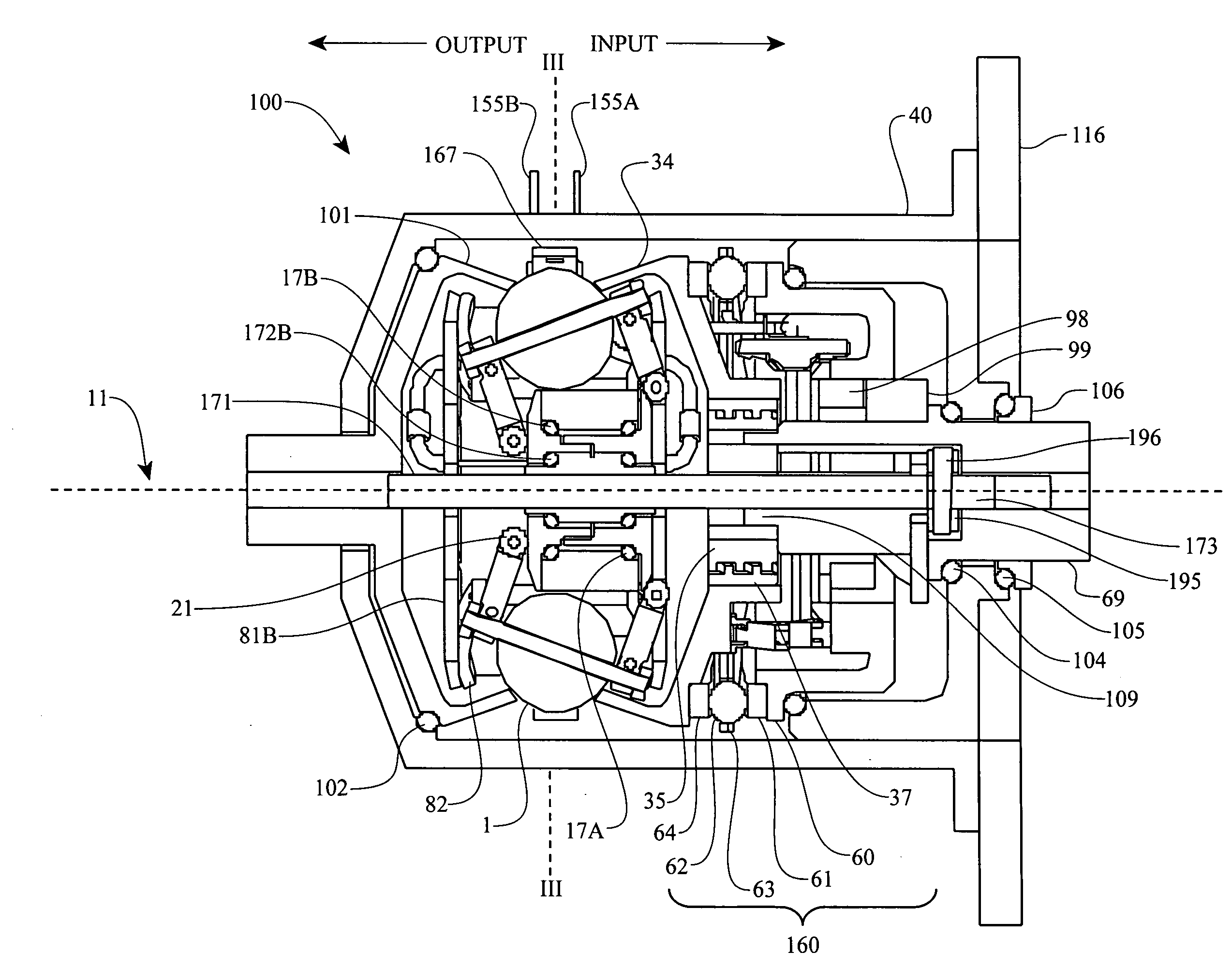
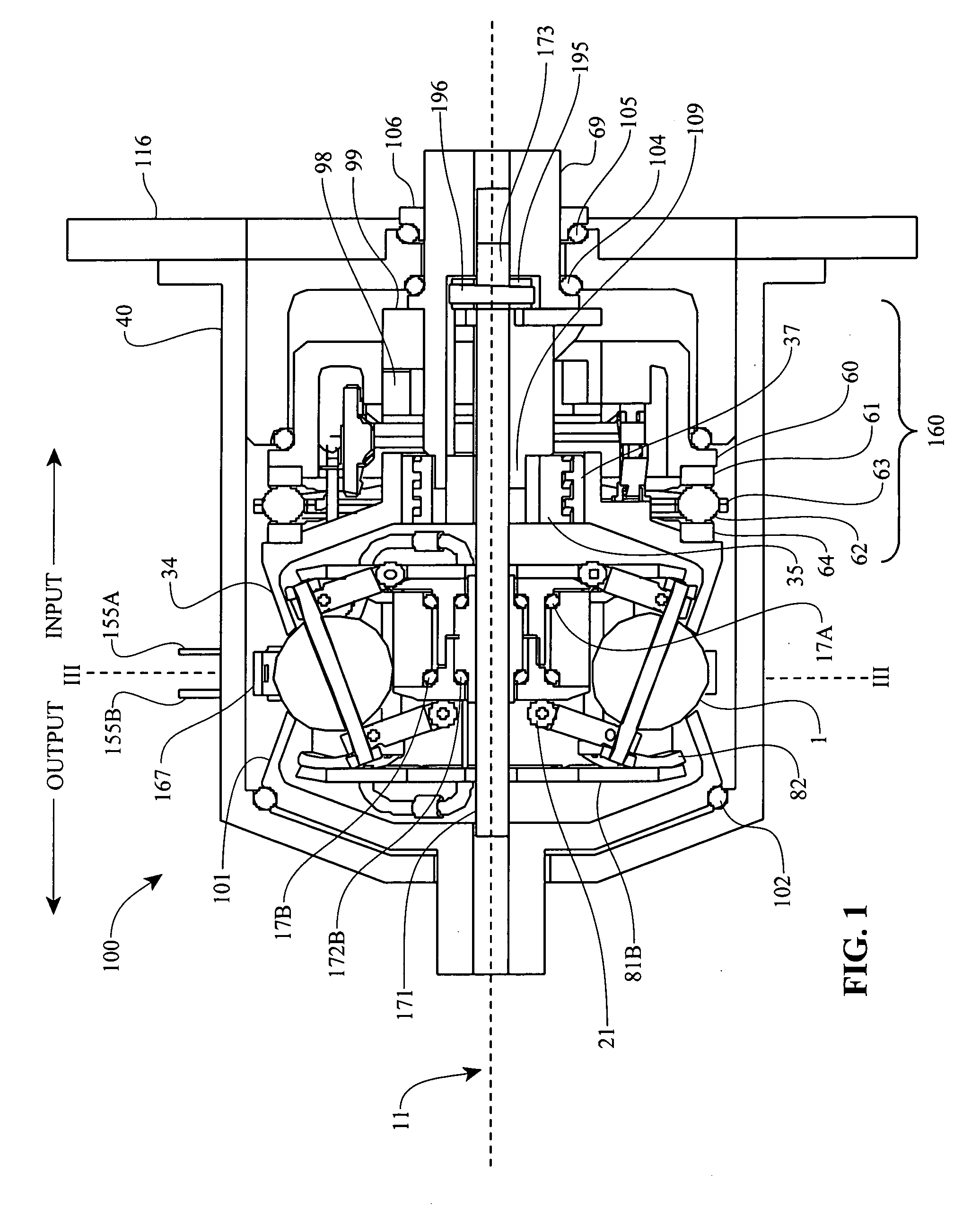
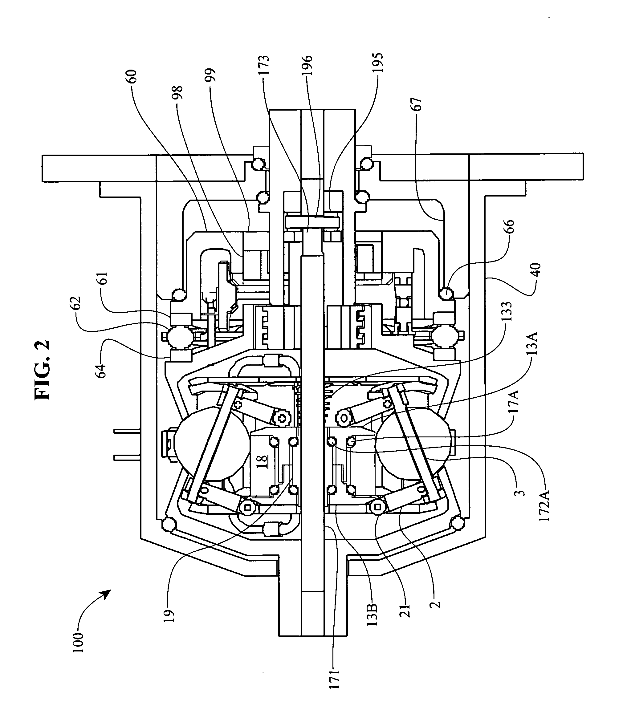
[0010]In yet another aspect, a variable speed transmission is disclosed comprising; a longitudinal axis, a plurality of balls distributed radially about the longitudinal axis, each ball having a tiltable axis about which it rotates, a rotatable input disc positioned adjacent to the balls and in contact with each of the balls, a fixed output disc positioned adjacent to the balls opposite the input disc and in contact with each of the balls, a rotatable idler having a constant outside diameter and positioned radially inward of and in contact with each of the balls, a cage, adapted to maintain the radial position and axial alignment of the balls and that is rotatable about the longitudinal axis, and an idler shaft connected to the idler adapted to receive a torque output from the idler and transmit the torque output out of the transmission.

[0011]For use with ...


PUM


Abstract

A transmission having a plurality of tilting balls and opposing input and output discs provides an infinite number of speed combinations over its transmission ratio range. The transmission provides multiple powerpaths and can be combined with electrical components to provide motor / generator functionality, which reduces the overall size and complexity of the motor and transmission compared to when they are constructed separately. In one embodiment, rotatable components of a continuously variable transmission are coupled separately to an electrical rotor and to an electrical stator so that the rotor and stator rotate simultaneously in opposite directions relative to one another. In other embodiments, an electrical rotor is configured to transfer torque to or from a disc that is in contact with a plurality of speed adjusters, while an electrical stator is configured to transfer torque to a shaft that is operationally coupled to the speed adjusters via an idler.

Description

RELATED APPLICATIONS[0001]This application is a continuation of U.S. patent application Ser. No. 11 / 585,677, filed on Oct. 24, 2006, which claims the benefit of U.S. Provisional Applications No. 60 / 730,995 and No. 60 / 731,362, both of which were filed on Oct. 28, 2005. Each of above-identified applications is hereby inculpated by reference in its entirety.BACKGROUND OF THE INVENTION[0002]1. Field of the Invention[0003]The field of the inventive embodiments relates generally to systems and methods for electromechanical or electromotive drives, and more particularly the inventive embodiments relate to drives that utilize methods and assemblies that integrate electrical devices and mechanical transmissions.[0004]2. Description of the Related Art[0005]In order to provide a continuously variable transmission, various traction roller transmissions in which power is transmitted through traction rollers supported in a housing between torque input and output discs have been developed. In such...

Claims


Application Information

Patent Timeline
Patent Type & Authority Applications(United States)
IPC IPC(8): F16H61/32B60W10/11
CPCB60K6/26B60K6/36B60K6/405B60K6/48B60K6/543B62M6/65F16H15/52H02K7/116Y02T10/6221H02K7/10F16H15/40F16H15/28Y02T10/62Y10S903/91Y10S903/918Y10S903/945B60K6/485B60K17/06B60K6/365B60W20/30B60Y2200/92B60Y2400/72B60Y2400/73F16H15/503F16H61/6649F16H2061/6644H02P9/06
Inventor MILLER, DONALD C.
Owner FALLBROOK INTPROP COMPANY
Why Eureka
Try Eureka