
Configurable locomotive

a locomotive and configuration technology, applied in the direction of locomotives, transportation and packaging, signalling indicators on vehicles, etc., can solve the problems of inability of railroad dispatchers to make available the best-suited locomotive for a particular mission, a significant amount of idle time of the switcher locomotive, and less than optimal configuration

Inactive Publication Date: 2005-06-09
GE GLOBAL SOURCING LLC
View PDF14 Cites 127 Cited by
  • Summary
  • Abstract
  • Description
  • Claims
  • Application Information

AI Technical Summary

Problems solved by technology

Modern railroad locomotives are complex vehicles containing multiple operating systems including sophisticated computerized controls responsive to a large number of input variables.
A switcher locomotive may also spend a significant amount of time idling, whereas road locomotives must operate for long periods at high power levels.
Railroad mission requirements are affected by numerous variables including customer demand, weather, equipment availability, personnel availability, government regulations, etc., and it is often impossible for a railroad dispatcher to make available the best-suited locomotive for a particular mission.
As a result, a locomotive originally assembled with the configuration suited for an initial intended mission will provide less-than-optimal configuration when placed into service for another and different mission, and typically the best a dispatcher is able to do is to provide a locomotive that presents a good compromise of capabilities to meet a range of different (and often competing) mission requirements.
However, the road locomotive may be configured to operate using a number of traction motors in excess of the number needed for switching operations, thus resulting in unnecessary wear on motors that are not really needed to satisfy the mission requirements.

Method used


Image

  • Configurable locomotive
  • Configurable locomotive
  • Configurable locomotive

Examples


Embodiment Construction

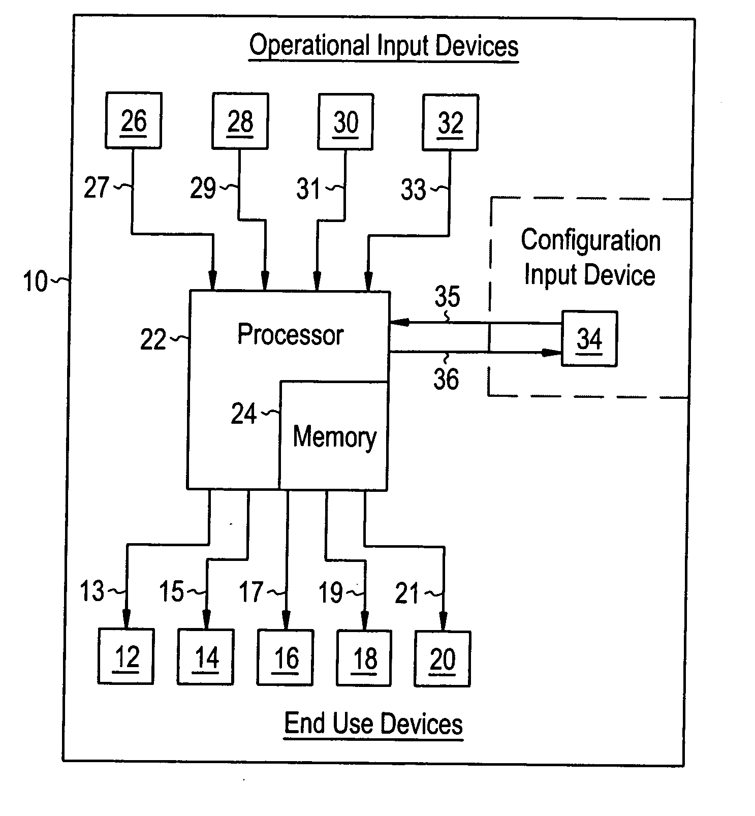
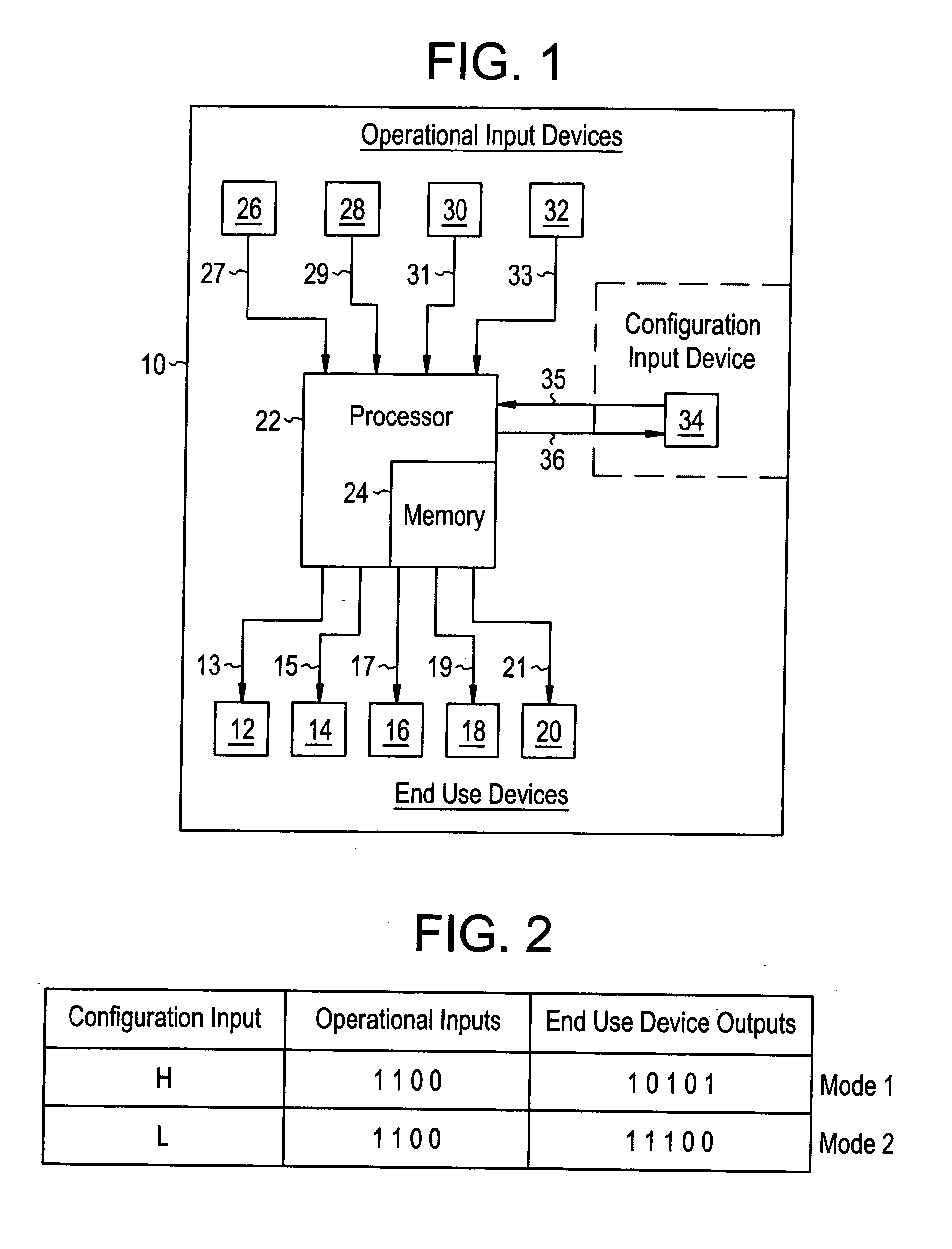
[0013]FIG. 1 is a block diagram of a control system of a locomotive 10 that can be operated in one of several configurations in order to better match the locomotive 10 to a particular mission. The term configuration is used herein to describe the overall operating profile of the locomotive, including important operating characteristics and the manner in which the operating systems of the locomotive are controlled in response to operational inputs. A locomotive's configuration may include performance variables such as the peak output rating of the locomotive engine, the correlation between the throttle notch settings and the percentage of full power generated, engine emissions curves, acoustic emissions, electromagnetic emissions, the number of traction motors used, fuel economy performance, adhesion limits, the organization, presentation and functionality of operator controls, communications protocol, auxiliary functions, etc.

[0014] The operating systems of a locomotive include a p...


PUM


Abstract

A locomotive (10) is operable in two or more distinct configurations, with the change in configuration being response to a configuration input signal (35). A locomotive configuration is represented by the set of end use device control signals (13) that are generated by the locomotive control systems (22) in response to the respective set of operational input values (27). For a given set of operational input values, a first set of end use device control signals is generated when a configuration input has a first value, and a second set of end use device control signals is generated when a configuration input has a second value. The configuration input variable may be responsive to the locomotive location, a wayside device signal, an operator action or the health of the locomotive, for example. Locomotive configuration changes may include peak horsepower rating, number of engine cylinders fueled, number of throttle notch settings, adhesion limits, mission priorities or emission profile, for example.

Description

RELATED APPLICATIONS [0001] This application is a continuation-in-part of co-pending U.S. patent application Ser. No. 10 / 435,261 filed on May 9, 2003, titled “Multimode Hybrid Energy Railway Vehicle System and Method” (attorney docket 122059CIP). This application is also a continuation-in-part of co-pending U.S. patent application Ser. No. 10 / 354,638 filed on Jan. 30, 2003, titled “System and Method for Selectively Limiting Tractive Effort to Facilitate Train Control” (attorney docket 5025), which in turn claims benefit of the Feb. 28, 2002 filing date of U.S. provisional patent application No. 60 / 319,128. This application also claims benefit of the Jul. 23, 2004 filing date of U.S. provisional patent application No. 60 / 590,853 title “Locomotive Control System and Method” (attorney docket 158334). Each of these previously filed applications is incorporated by reference herein.FIELD OF THE INVENTION [0002] This invention relates generally to the field of railroad locomotives. BACKGRO...

Claims


Application Information

Patent Timeline
IPC IPC(8): B60L15/32B61L15/00
CPCB60L15/32B61L15/0072B60L2200/26B61L2205/04B61L15/0081
Inventor KUMAR, AJITHSHAFFER, GLENNDAUM, WOLFGANGHILL, LEONARDCORRY, JAMES GLENWOLF, DANIELKELLNER, STEVEN ANDREW
Owner GE GLOBAL SOURCING LLC
Learn More