Apparatus and method for determining image region

a technology of image region and image, applied in the field of apparatus and a method for determining image region, can solve the problems of flicker noise, increase the memory capacity of the storage device that is installed, and increase the circuit scale, so as to prevent the memory capacity of the memory device, enhance the determining accuracy, and increase the determining accuracy

Inactive Publication Date: 2005-06-09
SONY CORP
View PDF12 Cites 1 Cited by
  • Summary
  • Abstract
  • Description
  • Claims
  • Application Information

AI Technical Summary

Benefits of technology

[0024] Thus, finally determining that the target pixel position is included in either a motion region or a still region by using the history information of such other pixel positions as well allows the determining accuracy to be enhanced. If the determining accuracy is not required as to be such the case, setting the threshold value of the above consecutive time used for determining that the target pixel position is included in a still region to be smaller allows a response speed for determining that it is included in a still region to be enhanced.
[0025] According to the invention, it is finally determined that the target (interpolation or the like) pixel position is included in either a motion region or a still region, based on the determined result of the target pixel position and the history information on the determined result, which corresponds to the target pixel position, of past predetermined time(s). This allows determining accuracy to be increased with memory capacity of the memory device being prevented from increasing vastly.

Problems solved by technology

Since the interlaced signal constitutes a signal of one frame in which signals of lines are arranged one after the other as signals of odd field and even field, a flicker noise occurs if a fine horizontal line stays in an image.
This causes memory capacity in storage device that is installed to be more increased, thus to enlarge a circuit scale.

Method used


Image

  • Apparatus and method for determining image region
  • Apparatus and method for determining image region
  • Apparatus and method for determining image region

Examples


Embodiment Construction

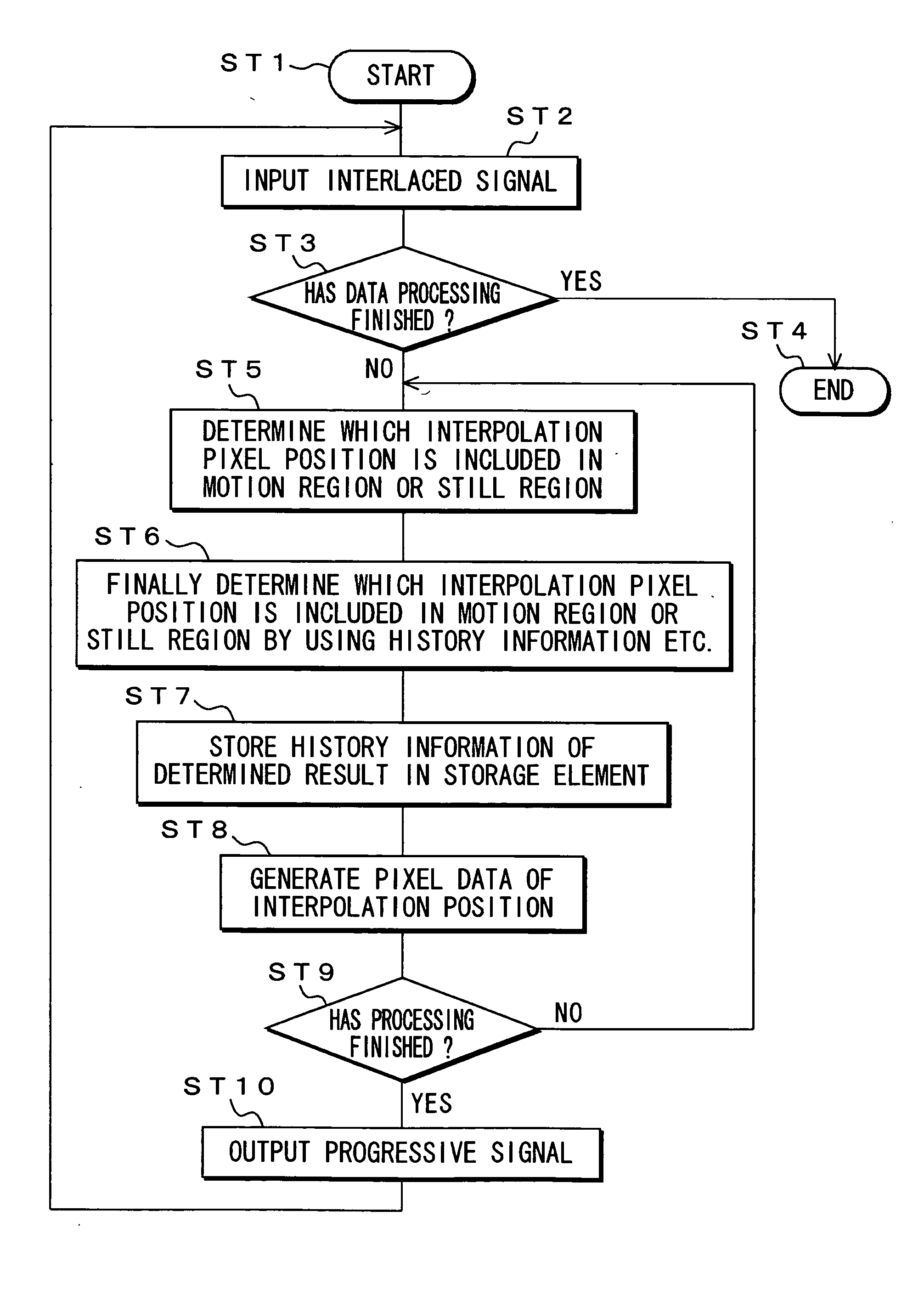
[0036] The embodiments according to the invention will now be described in detail with reference to the drawings. FIG. 1 shows a configuration of an embodiment of image display apparatus 100 according to the invention.

[0037] The image display apparatus 100 comprises an input terminal 101 for receiving an image signal V0 of interlaced signal, and an IP conversion unit 102 for converting the interlaced image signal V0 into image signal Vp of progressive signal. The IP conversion unit 102 connects memories (storage devices) 103 and 104.

[0038] The memory 103 has a memory capacity that is capable of storing pixel data of at least 2 fields and functions as being delay means for delaying it a period of one field or two fields. The memory 104 stores history information of past predetermined time(s) of a determined result RS1 that it is included in either a motion region or a still region, which corresponds to each interpolation pixel position of odd and even fields in the interlaced signa...


PUM


Abstract

A determining portion first determines which an interpolation pixel position (a target position of image signal) which is positioned in a field that precedes a current field by one field is included in a motion region or a still region by using an image signal of current field and an image signal of two fields before to obtain a determine result of this time. The determining portion finally determines which the interpolation pixel position is included in a motion region or a still region based on the determined result of this time and the history information, which is read out of a memory through a history-information-read-processing portion, on a determined result of past predetermined times(s) corresponding to the interpolation pixel position to obtain a determined result. The memory stores the history information on a determined result of past predetermined times(s) corresponding to each interpolation pixel position.

Description

BACKGROUND OF THE INVENTION [0001] 1. Field of the Invention [0002] The invention relates to an apparatus and a method for determining image region. More particularly, it relates to an apparatus and a method for determining that a target position of the image signal is included in either a motion region or a still region, and an apparatus and a method for processing an image signal. [0003] 2. Description of Related Art [0004] An interlace-scheme image signal (interlaced signal) is employed in various image signals used in a television apparatus, a video apparatus and the like. A progressive-scheme image signal (progressive signal), on the other hands, is employed in image signals used in a computer. Thus, for example, in order to display images for the computer and the television on a computer display screen, the interlaced signal is converted into the progressive signal. [0005] Since the interlaced signal constitutes a signal of one frame in which signals of lines are arranged one ...

Claims


Application Information

Patent Timeline
Patent Type & Authority Applications(United States)
IPC IPC(8): H04N5/14H04N11/02H04N7/01H04N11/04
CPCH04N7/012H04N5/144
Inventor TANAKA, TETSURO
Owner SONY CORP
Why Eureka
Try Eureka