Method for determining the distribution of an imaging agent

a technology of imaging agent and distribution method, which is applied in the field of imaging agent distribution measurement, can solve the problems of inhomogeneous uptake, slow uptake, and inability to accurately represent the uptake, so as to improve the accuracy of the method, improve the accuracy, and reduce the complexity of the imaging system

Active Publication Date: 2015-11-03
KONINKLJIJKE PHILIPS NV
View PDF6 Cites 0 Cited by
  • Summary
  • Abstract
  • Description
  • Claims
  • Application Information

AI Technical Summary

Benefits of technology

[0009]It is an object of the invention to provide an improved, faster and more accurate method for determining the activity of an imaging agent such as a radiotracer within the imaging region of an imaging system. It is a further object of the invention to provide a more accurate method for determining the required dose of therapy agent that is subsequently administered to a body during a treatment stage. Other objects of the invention include the provision of an imaging protocol with reduced throughput time, and the use of less complex imaging systems than are currently employed.
[0010]This object is achieved as claimed in claim 1 by the use of the method in which additional and improved imaging agent distribution basis functions that better approximate the actual activity distribution during the progression of imaging agent uptake in the body are assigned to compartments within the volume of interest. The imaging agent distribution basis functions comprise a representation of the three-dimensional imaging agent activity in each compartment by the product of a scaling factor and a non-affine transformation of a template imaging agent activity wherein the template imaging agent activity is determined from a three-dimensional functional image of the volume. The accuracy of determining the activity of an imaging agent within the imaging region of an imaging system, and the accuracy of a therapy agent calculation made in accordance with the invention are both improved through the use of this new representation. A reduction of processing time and thus improved patient throughput is achieved through the use of this model which provides a better fit with a measured planar image of the imaging agent activity. Further improvements in the accuracy of calculating the necessary dose of a therapy agent made in accordance with the invention, and a reduction in processing time result from improvements to the segmentation of the three-dimensional functional image into compartments.
[0011]The improved method of claim 1 originates from the realization that the accumulation of an imaging agent such as a radiotracer within particular regions of an organ occurs at surprisingly elevated rates at certain points in time. During the initial phase immediately after the imaging agent has been administered to the body the uptake can be relatively uniform within a particular organ yielding a more or less homogeneous imaging agent distribution. Toward the final imaging stages the imaging agent activity typically decays to a more or less homogeneous activity. However during the uptake phase the imaging agent has been found to accumulate at elevated rates at particular regions within an organ. This may be at a particular tumour site, or in a particular region within a tumour. At other positions within particular organs the uptake has been found to be particularly slow. Thus the assumptions of a homogeneous imaging agent compartment distribution made in previous approaches to model the imaging agent distribution such as such as QPLANAR and EQPLANAR restrict the accuracy of these approaches. Likewise, imaging agent distribution basis functions as determined from a three-dimensional functional image and held constant for all scintigraphies may inadequately represent the inhomogeneous uptake. By contrast the representation of the three-dimensional imaging agent activity in each compartment by the product of a scaling factor and a non-affine transformation of a template imaging agent activity wherein the template imaging agent activity is determined from a three-dimensional functional image of the volume in the present invention can be used to either accentuate or suppress the modelled projected imaging agent activity at particular voxels within the imaging region that are associated with a high activity or a low activity respectively in the functional image without prior knowledge about particular sites of increased or decreased uptake. The choice of appropriate non-affine activity transformations can be made depending on the patient and the disease state, separately for each organ, for each time-point, and for each two-dimensional plane, to increase the likelihood between the projected imaging agent activity and the measured imaging agent activity. Consequently a better fit is obtained between the projected imaging agent activity and the measured activity on a planar surface such as a scintigraphy, and an improved estimate of the activity within a compartment can be made.

Problems solved by technology

At other positions within particular organs the uptake has been found to be particularly slow.
Thus the assumptions of a homogeneous imaging agent compartment distribution made in previous approaches to model the imaging agent distribution such as such as QPLANAR and EQPLANAR restrict the accuracy of these approaches.
Likewise, imaging agent distribution basis functions as determined from a three-dimensional functional image and held constant for all scintigraphies may inadequately represent the inhomogeneous uptake.

Method used


Image

  • Method for determining the distribution of an imaging agent
  • Method for determining the distribution of an imaging agent
  • Method for determining the distribution of an imaging agent

Examples


first embodiment

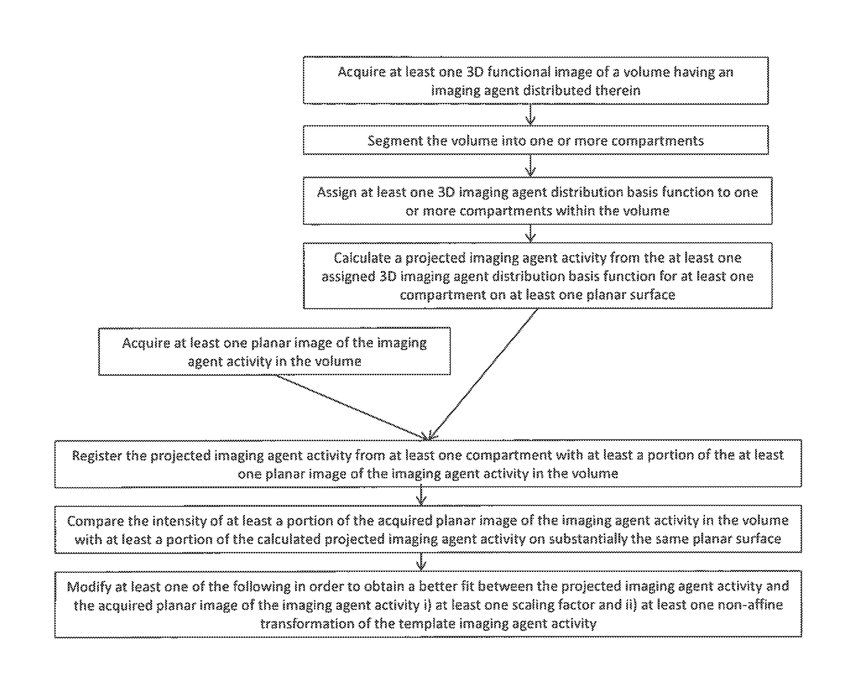
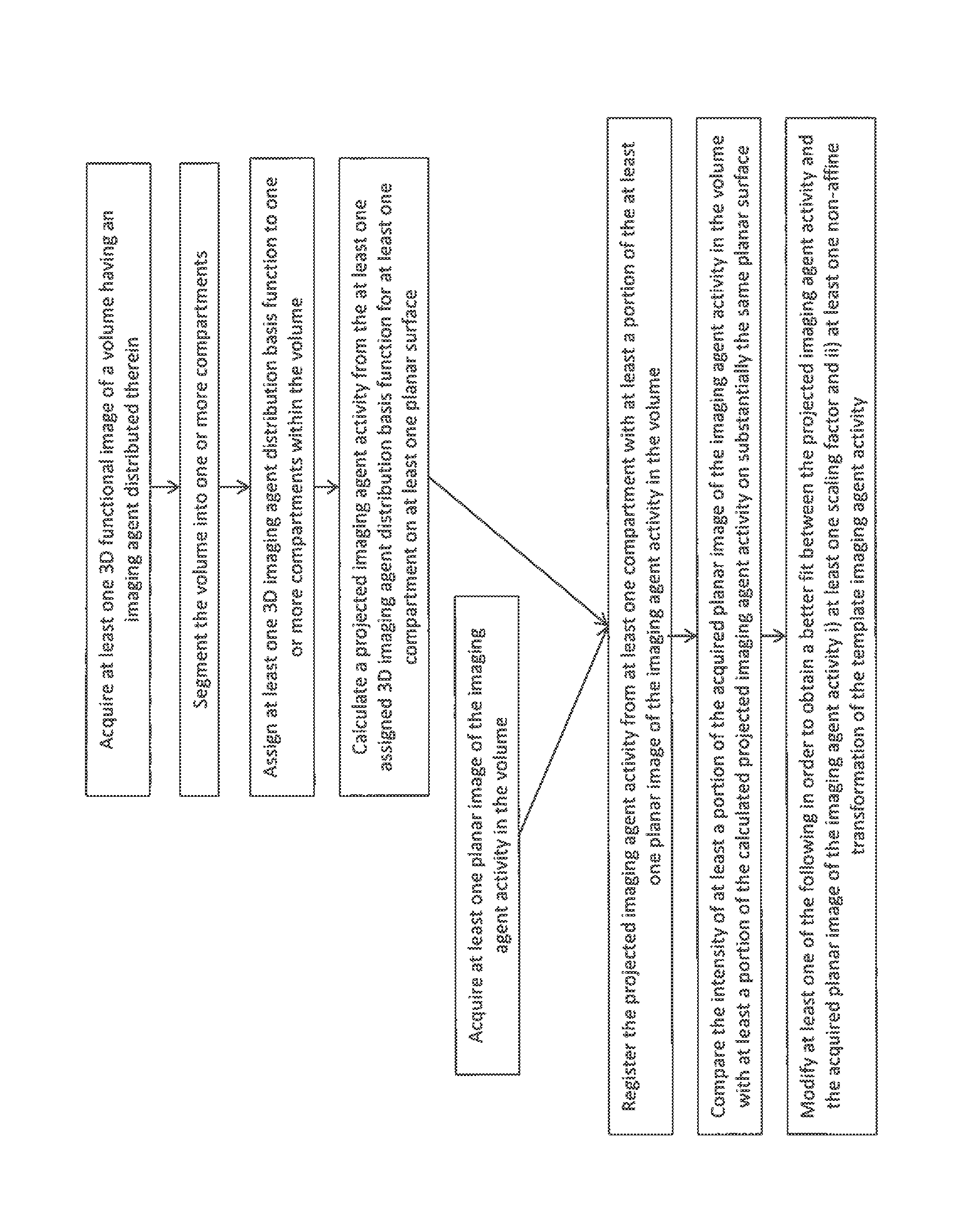
[0039]In the invention the imaging agent activity in a compartment is represented by a single non-affine transformation of the template imaging agent activity as determined from a functional image of the volume. Thus taking for example Equation 2 above, the activity resulting from the imaging agent distribution basis function in the first compartment (n=1) can be represented by the matrix:

B1,1(x,y,z)=k1,1·(C(x,y,z)*S1(x,y,z))2  Equation 4

for the exemplary case where the non-affine activity transformation of a square power law is used and k1,1 is a scaling factor associated with compartment 1 and the imaging agent distribution basis function 1.

second embodiment

[0040]In the invention the imaging agent activity in a compartment is represented by the combination of a non-affine transformation and an affine transformation of the template imaging agent activity as determined from a functional image of the volume. Thus taking for example Equation 2 above, the activity resulting from the imaging agent distribution in the first compartment (n=1) may be represented by the matrix:

T1=k1,1·(C(x,y,z)*S1(x,y,z))2+k1,2·(C(x,y,z)*S1(x,y,z))+k1,3*S1(x,y,z)  Equation 5

for the exemplary case where the non-affine activity transformation of a square power law is used and wherein k1,1, k1,2, k1,3 are scaling factors associated with compartment 1. The scaling factors in either embodiment may be adjusted independently in order to improve the correspondence between the calculated projected imaging agent activity and the intensity of the acquired planar image or scintigraphy. This second embodiment is well suited to fitting to the planar image when a locally high ...


PUM


Abstract

The present invention relates to a method for determining the distribution of an imaging agent in a volume. The method comprises the acquisition of at least one three-dimensional functional image of the volume; the segmentation of the volume into one or more compartments; the representation of the three-dimensional imaging agent activity from the functional image by the product of a scaling factor and a non-affine transformation of a template imaging agent activity; the calculation of a projected imaging agent activity from the thus represented imaging agent activity on a planar surface; the acquisition of a planar image of the imaging agent activity in the volume; the registration of the projected imaging agent activity with the planar image; the comparison of the acquired planar image with the calculated projected imaging agent activity; and the modification of the representation of the three-dimensional imaging agent activity.

Description

CROSS REFERENCE TO RELATED APPLICATIONS[0001]This application is a national filing of PCT application Serial No. PCT / IB2013 / 056754, filed Aug. 20, 2013, published as WO 2014 / 030119 A1 on Feb. 27, 2014, which claims the benefit of U.S. provisional application Ser. No. 61 / 691,874 filed Aug. 22, 2012 and EP provisional application serial no. 12181291.1 filed Aug. 22, 2012, both of which are incorporated herein by reference.FIELD OF THE INVENTION[0002]The invention relates to a method for analysing images from medical imaging systems. More specifically the invention finds application in the field of imaging agent distribution measurement, and even more specifically the invention can be applied to measure the distribution of a radiotracer in the field of dose optimization in the delivery of targeted radiotherapy.BACKGROUND OF THE INVENTION[0003]In the field of medical imaging the measurement of radiotracer distributions within a body is used to indicate the functioning of various biologi...

Claims


Application Information

Patent Timeline
Patent Type & Authority Patents(United States)
IPC IPC(8): G06K9/00H04N13/02G06T3/00G06K9/62G06T7/00
CPCG06T7/0012G06K9/6215G06T3/00G06T7/0016G06T7/0081H04N13/0203G06T2207/10104G06T2207/10108G06T2207/10128G06T2207/30004H04N13/204G06F18/22
Inventor BERKER, YANNICK
Owner KONINKLJIJKE PHILIPS NV
Why Eureka
Try Eureka